Lighting device circuit with series-connected solid state light emitters and current regulator

a lighting device and solid-state light technology, applied in lighting and heating apparatus, process and machine control, instruments, etc., can solve the problems of waste heat dissipation, high efficiency of this method, and excess voltage, and achieve high efficiency, high lumen, and good efficacy

Active Publication Date: 2010-12-14
IDEAL IND LIGHTING LLC
View PDF54 Cites 60 Cited by
  • Summary
  • Abstract
  • Description
  • Claims
  • Application Information

AI Technical Summary

Benefits of technology

[0029]Another method which has been employed is to use a transformer to first reduce the line AC voltage to a much smaller voltage, a voltage approximately the same as required by the solid state light emitters. This low voltage AC is then rectified to DC and typically series current regulated through a semiconductor chip (LM317) and applied to the string of solid state light emitters. This arrangement provides better efficiency, but the efficiency is still typically only about 50% due to losses in the transformer.
[0033]Additionally, in the case of downlights, the efficiency of the heatsinks is significantly reduced because the heated air is trapped in the downlight fixture.
[0035]There is a need for a light bulb or light fixture constructed from solid state light emitters that connects to power supply (and optionally further includes cooling means) and is highly efficient, attractive and lightweight.
[0036]The present invention is directed to a high lumen (e.g., >700 lumens ) and good efficacy (e.g., >40 lumen / watt) light fixture or light bulb which in some embodiments includes a power regulator in the fixture or bulb, i.e. which does not use a separate power regulator, to adapt the line voltage (e.g., 110 VAC, 117 VAC, 220 VAC, 277 VAC, etc.) to voltage and current requirements of the solid state light emitters. A major issue is the efficiency of the power supply and the heat generated by this loss in efficiency, as well as the heat generated by the solid state light emitters themselves.
[0037]In some embodiments according to the present invention, solid state light emitters (e.g., LEDs) are arranged in series in strings of sufficient length that the forward voltage across the solid state light emitter string is slightly less then the rectified AC main supply. By matching the forward voltage of the string to the line voltage, it is possible to minimize the amount of power lost in the conversion and regulation.

Problems solved by technology

A major disadvantage of such an arrangement is that the excess voltage; i.e. the difference between the line voltage (e.g., 110 V or 117 V) and the voltage across the solid state light emitters (e.g., in the case of LEDs, typically 2-4 V or ˜30 V if 9 LEDs are connected in series) is dissipated as wasted heat.
The efficiency of this method is very low; efficacy using this method can be as low as 3 lumens per watt.
This arrangement provides better efficiency, but the efficiency is still typically only about 50% due to losses in the transformer.

Method used


Image

  • Lighting device circuit with series-connected solid state light emitters and current regulator
  • Lighting device circuit with series-connected solid state light emitters and current regulator
  • Lighting device circuit with series-connected solid state light emitters and current regulator

Examples


Embodiment Construction

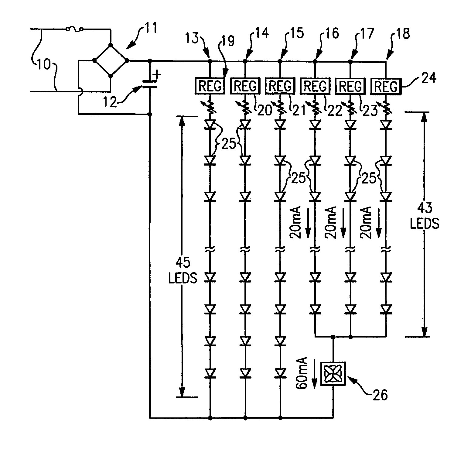
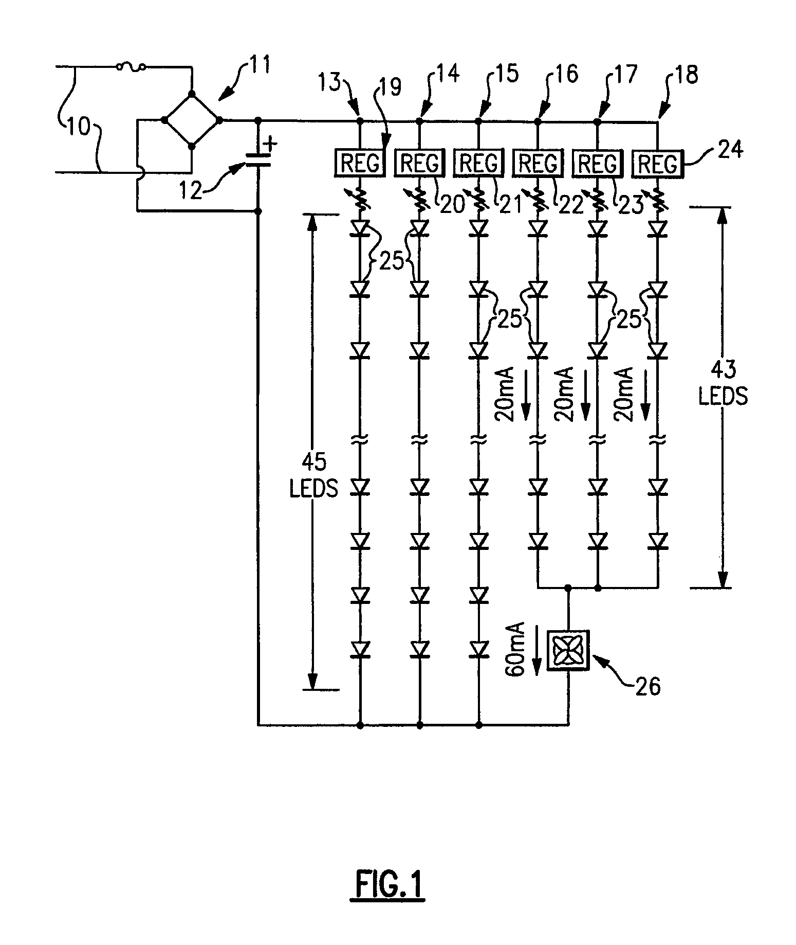
[0057]As noted above, in a first aspect according to the present invention, there is provided a circuit for a lighting device, the circuit comprising at least a first sub-circuit which comprises at least a first series current regulator and a first group of solid state light emitters.

[0058]The expression “sub-circuit”, as used herein, means circuitry comprising one or more components or features contained within a circuit (under this terminology, a circuit can itself consist of a single sub-circuit).

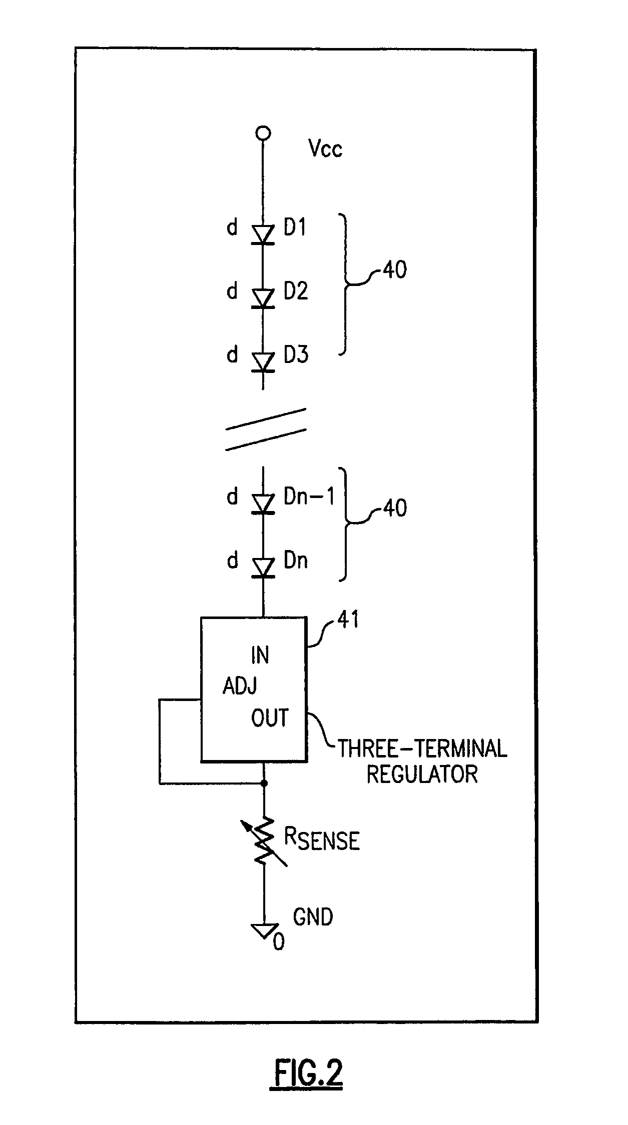
[0059]Any type of series current regulator can be employed in the circuits according to the present invention, and where plural series current regulators are employed, the respective series current regulators can be of similar types or can include two or more different types. Persons of skill in the art are familiar with, and have access to, a variety of types of series current regulators, and any such series current regulators can be employed in the circuits according to the present inv...


PUM


Abstract

A circuit for a lighting device comprises a sub-circuit which comprises a series current regulator and a group of solid state light emitters. The current regulator and the solid state light emitters are arranged in series. In some embodiments, the circuit further comprises a fan electrically connected in series in the sub-circuit. In some embodiments, the circuit further comprises a second sub-circuit which comprises a second series current regulator and a second group of solid state light emitters, the first sub-circuit and the second sub-circuit being arranged in parallel. In some embodiments, an anode of the series current regulator is electrically connected to a cathode of one of the solid state light emitters. Also, methods of lighting wherein a sum of voltage drops across light emitters and a current regulator is in the range of from 1.2 to 1.6 times the line voltage.

Description

CROSS-REFERENCE TO RELATED APPLICATIONS[0001]This application claims the benefit of U.S. Provisional Patent Application No. 60 / 761,879, filed Jan. 25, 2006, the entirety of which is incorporated herein by reference.[0002]This application claims the benefit of U.S. Provisional Patent Application No. 60 / 809,959, filed Jun. 1, 2006, the entirety of which is incorporated herein by reference.FIELD OF THE INVENTION[0003]The present invention is directed to a circuit for a lighting device, more particularly, a circuit for a lighting device which includes a plurality of solid state light emitters. The present invention is also directed to a method of lighting using a circuit which includes a plurality of solid state light emitters.BACKGROUND OF THE INVENTION[0004]A large proportion (some estimates are as high as twenty-five percent) of the electricity generated in the United States each year goes to lighting. Accordingly, there is an ongoing need to provide lighting which is more energy-eff...

Claims


Application Information

Patent Timeline
Patent Type & Authority Patents(United States)
IPC IPC(8): H05B37/00H05B44/00
CPCH05B33/0812H05B33/0827Y02B20/343Y02B20/345H05B45/395H05B45/46Y02B20/30
Inventor COLEMAN, THOMAS G.MYERS, PETER J.VAN DE VEN, ANTONY PAULNEGLEY, GERALD H.
Owner IDEAL IND LIGHTING LLC
Why Eureka
Try Eureka