Inverter device
a technology of inverter and phase current, which is applied in the direction of motor/generator/converter stopper, dynamo-electric converter control, instruments, etc., can solve the problems of unsatisfactory noise and vibration, and achieve high frequency, high reliability of operation, and suppress noise and vibration
- Summary
- Abstract
- Description
- Claims
- Application Information
AI Technical Summary
Benefits of technology
Problems solved by technology
Method used
Image
Examples
first exemplary embodiment
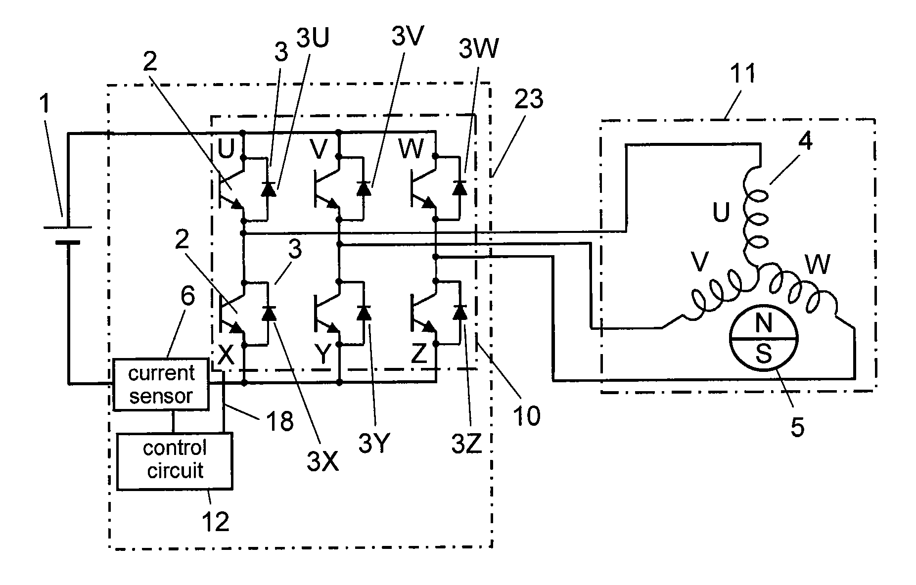
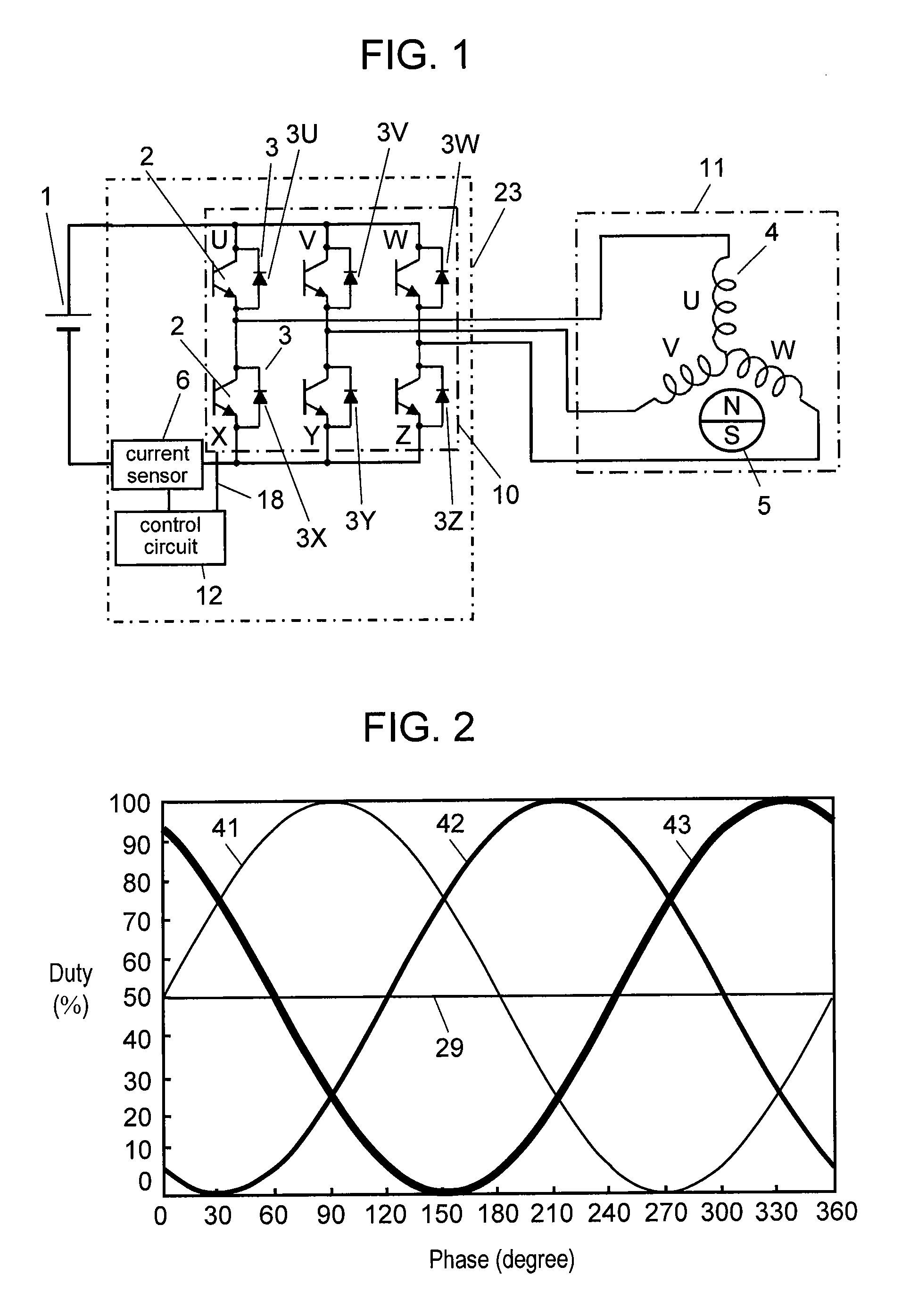
[0075]FIG. 1 is an electric circuit diagram showing an inverter device and the peripheral structure in accordance with the first exemplary embodiment of the present invention. Receiving voltage from current sensor 6 disposed on a power source line, control circuit 12 of inverter device 23 detects phase current. Control circuit 12 detects current in two phases and calculates the current value of the rest of the three phases from the detected two current values. In the calculation, Kirchhoff's law is applied to a neutral point of stator winding 4.
[0076]Using the three current values, control circuit 12 detects the position of magnet rotor 5 that constitutes sensorless DC brushless motor 11 (hereinafter, motor 11) by calculating induced voltage of stator winding 4. According to a revolution speed instruction signal (not shown) and the like, control circuit 12 controls switching elements 2 of inverter circuit 10 so that DC voltage from battery 1 is switched by PWM driving. Through the m...
second exemplary embodiment
[0104]The structure of the second exemplary embodiment will be described with reference to FIGS. 21 through 24. FIG. 21 shows behavior of each phase current in a case where a first correction is applied to the carrier cycle on the left and a second correction is applied to the carrier cycle on the right. The left-side carrier cycle is corrected in a manner that 2δ is added to the beginning of the ON period of the W-phase in FIG. 18 and 2δ is also added to the U-phase and the V-phase so as to be evenly shared between the beginning and the end of the ON period. The correction allows the current sensor to have time δ for detecting the W-phase current in the beginning and the end of the ON period, so that the W-phase current is detectable. In the left-side carrier cycle, a negative-going ripple appears in U-phase current iU and V-phase current iV, whereas a positive-going ripple appears in W-phase current iW.
[0105]On the other hand, the right-side carrier cycle is corrected in a manner ...
third exemplary embodiment
[0110]The structure of the third exemplary embodiment will be described with reference to FIGS. 25 through 29. According to the structure of the embodiment, current in two phases is detected on the four-carrier-cycle basis, i.e., one phase-current is detected on the two-carrier-cycle basis.
[0111]The left-side carrier cycle of FIG. 25 is so formed that time δ is added to the beginning of the ON period of the W-phase in FIG. 18. The U-phase and the V-phase have no addition. The correction above allows the current sensor to have time δ for detecting the W-phase current in the beginning of the ON period, that is, the W-phase current is detectable. U-phase current iU and V-phase current iV change in the negative direction, whereas W-phase current iW changes in the positive direction. On the other hand, the right-side carrier cycle of FIG. 25 is so formed that time δ is subtracted from the beginning of the ON period of the W-phase in FIG. 18. The subtraction cancels out the addition provi...
PUM
 Abstract
Description
Claims
Application Information
 - R&D
- Intellectual Property
- Life Sciences
- Materials
- Tech Scout
- Unparalleled Data Quality
- Higher Quality Content
- 60% Fewer Hallucinations
Browse by: Latest US Patents, China's latest patents, Technical Efficacy Thesaurus, Application Domain, Technology Topic, Popular Technical Reports.
© 2025 PatSnap. All rights reserved.Legal|Privacy policy|Modern Slavery Act Transparency Statement|Sitemap|About US| Contact US: help@patsnap.com


