Rotation angle sensor

a technology of rotation angle and sensor, which is applied in the direction of instruments, mechanical measuring arrangements, calibration apparatus, etc., can solve the problems of inconvenient axial spacing, and achieve the effect of reliably keeping chemical and physical environmental conditions out of the housing, preventing non-contact coupling, and high accuracy

Inactive Publication Date: 2010-12-21
ASM AUTOMATION SENSORIK MESSTECHN GMBH
View PDF11 Cites 19 Cited by
  • Summary
  • Abstract
  • Description
  • Claims
  • Application Information

AI Technical Summary

Benefits of technology

[0017]Therefore, it is the object of the invention to provide a rotation angle sensor that is located in an enclosed housing without rotating pass through, still delivering a high quality signal.
[0018]Through the location of an additional intermediary element within a protected housing an additional component is required; however, through its precise bearings, within the housing like the sensor element, it is assured on the one hand, that both components are not in an area influenced by rough environmental conditions and that an exact geometric alignment of the two components relative to each other is preformed with respect to their axial distance and also with respect to the alignment of their rotational axes. This results in a very high transfer precision of rotation of an intermediary element into an electrically processable signal.

Problems solved by technology

A non-contacting coupling of the rotation indicator, in particular of a magnetic rotational indicator, through a wall of the housing to the intermediary element, allows for offsets of the rotational axes to a large extent, and also angular errors of the rotational axis relative to each other, and also incorrect axial spacing of the rotation indicator and the intermediary element.

Method used


Image

  • Rotation angle sensor
  • Rotation angle sensor
  • Rotation angle sensor

Examples


Embodiment Construction

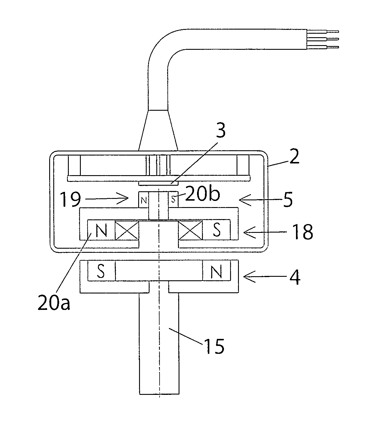
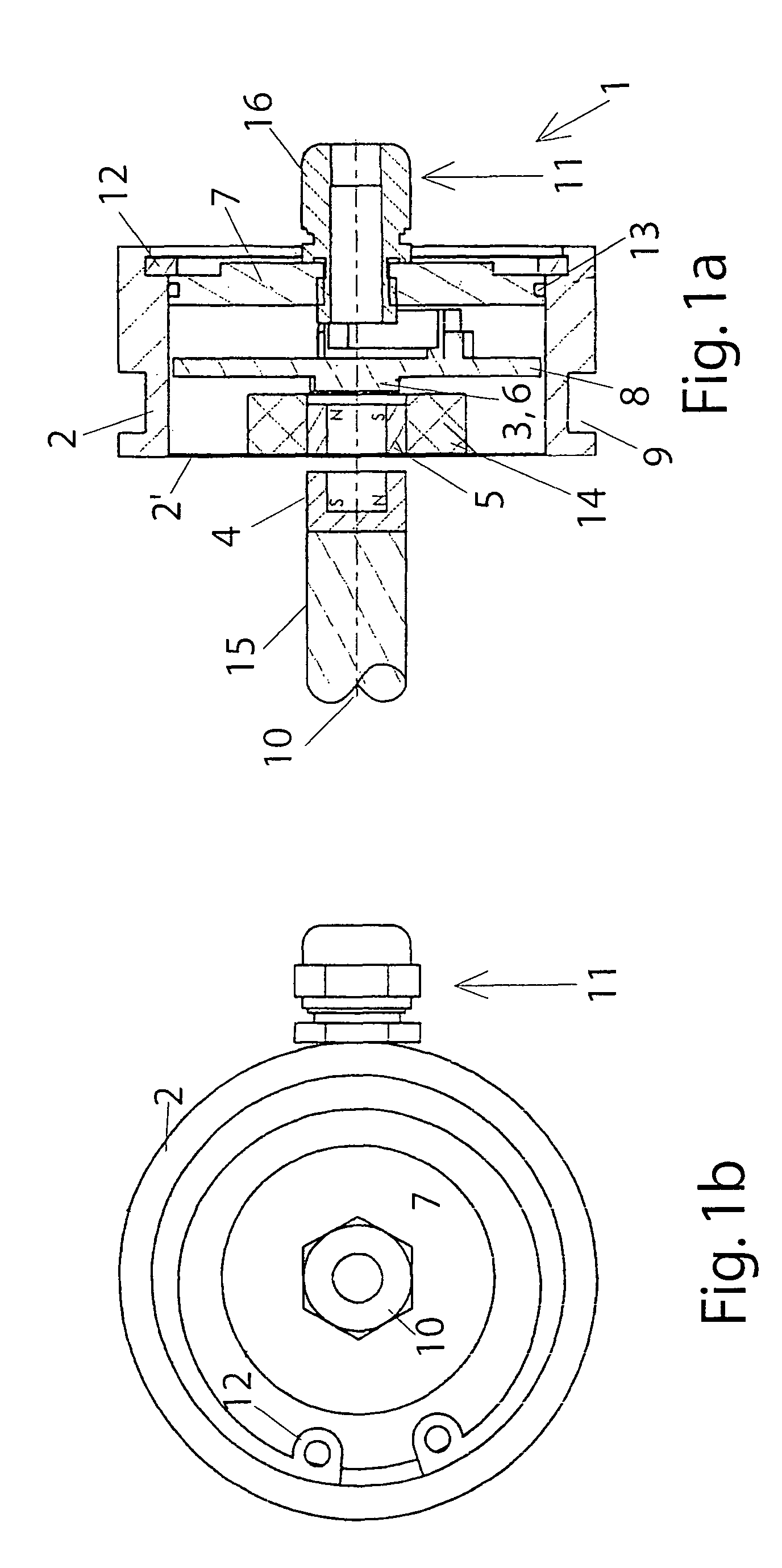
[0070]A rotation angle sensor is located, as can be seen in FIG. 1, in an interior of a pot-shaped housing 2 having a very thin frontal wall 2′ as a bottom of the pot. Housing 2 is completed through a cover 7 which abuts to an interior circumference of a wall of housing 2 through an O-ring 13 as a seal, and which is secured in it in axial direction through a snap ring 12.

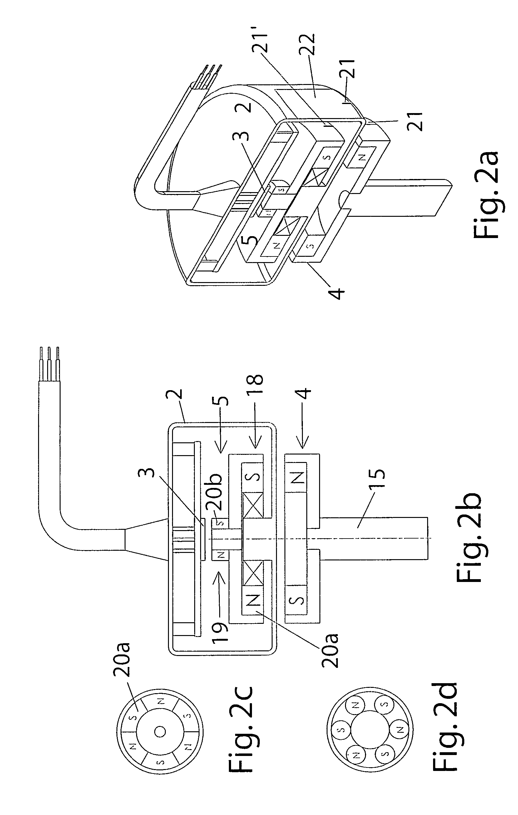
[0071]Directly at an inside of thin frontal wall 2′ a round intermediary element 5 is rotatably supported with its outer circumference in an annular bearing 14 inserted into an inside of thin frontal wall 2′, wherein an intermediary element 5 at least comprises a permanent magnet having at least two different poles being arranged behind each other in circumferential direction, and are preferably provided on the front face of an intermediary element pointing toward the interior of the housing, and also on the opposing front face of the intermediary element.

[0072]On a rotational axis 17 of intermediary element 5, whic...


PUM


Abstract

A rotation angle sensor is provided for determining mechanical angular positions and transposing them into signals transferable through electricity. The sensor includes a housing (2), a rotation indicator (4) located outside of the sensor housing (2a) so that it can rotate and coupled with the sensor element (3) so it operates in a non-contracting manner through the wall of the housing (2). A sensor element (3) is located in the interior of the housing (2). An intermediary element (5) is rotationally supported in the interior of the housing (2) between the sensor element (3) and the rotation indicator (4) and coupled to the rotation indicator (4) in a rotationally fixed, but non-contacting manner.

Description

CROSS-REFERENCES TO RELATED APPLICATIONS[0001]This application claims priority to Germany Patent Application Nos. 102005063071.4 filed 30 Dec. 2005 and 102006060213.7 filed 20 Dec. 2006.THE NAMES OF THE PARTIES TO A JOINT RESEARCH AGREEMENT[0002]Not ApplicableINCORPORATION-BY-REFERENCE OF MATERIAL SUBMITTED ON A COMPACT DISC[0003]Not ApplicableBACKGROUND OF THE INVENTION[0004]The invention regards rotation angle sensors for determining mechanical angular positions and transposing them into signals transferable through electricity.[0005]Such rotation angle sensors are known in various designs, operating through induction, magnetism, or opto-electronics.[0006]Thereby, the mechanical rotational positions of functional elements relative to the rotation angle sensor are detected and provided as electrical signals to an electric or electronic processing- and / or control unit.[0007]In particular, when such rotational angle sensors have to be used in rough operating conditions, the weak spot...

Claims


Application Information

Patent Timeline
Patent Type & Authority Patents(United States)
IPC IPC(8): G01B7/30
CPCG01D5/04G01D5/145
Inventor STEINICH, KLAUS MANFRED
Owner ASM AUTOMATION SENSORIK MESSTECHN GMBH
Why Eureka
Try Eureka