Ring oscillation circuit, delay time measuring circuit, testing circuit, clock generating circuit, image sensor, pulse generating circuit, semiconductor integrated circuit, and testing method thereof

a delay time and measuring circuit technology, applied in the direction of pulse technique, pulse characteristics measurement, instruments, etc., can solve the problems of difficult application of launch and capture clocks of high accuracy at a high speed from the lsi tester, insufficient measurement accuracy for testing timing accuracy at a high accuracy of not more than 100, etc., to accurately develop the delay time of the delay circuit, the effect of stably continuing the ring oscillation operation

Inactive Publication Date: 2010-12-21
SHARP KK
View PDF13 Cites 12 Cited by
  • Summary
  • Abstract
  • Description
  • Claims
  • Application Information

AI Technical Summary

Benefits of technology

[0058]The present invention has been made taking the problem caused by the ring oscillation operation due to the negative feedback and the problem in the delay test according to the conventional scan path method into consideration and the first object of which is to provide a ring oscillation circuit, which can operate the ring oscillation due to a positive feedback stably and continuously, the second object of which is to provide a delay time measuring circuit, which can accurately measure a delay time with respect to a rising edge or a falling edge by applying the ring oscillation operation due to a positive feedback, the third object of which is to provide a testing circuit, which can evaluate a timing accuracy such as a jitter or the like of a clock signal, which is generated by a PLL circuit or the like, with a high accuracy, and a clock generating circuit including this testing circuit, and the fourth object of which is to provide a pulse generating circuit, which can immediately start a delay test according to a scan path method and carry out the delay test at a high speed and with a high accuracy, and a semiconductor integrated circuit.Means for Solving the Problem
[0089]According to the semiconductor integrated circuit according to the above-described characteristic, since the semiconductor integrated circuit incorporates the pulse generating circuit of the above-described fifth or sixth characteristic, all problems 1) to 7) pointed out in Problem for Background Art 2 are solved. Therefore, it is possible to realize a semiconductor integrated circuit, capable of conducting the delay test according to the scan path method at a high speed and with a high accuracy.

Problems solved by technology

It is popular that an external measuring device such as a high-performance analog LSI tester and a measurement tool or the like is used for measuring the timing accuracy of jitter or the like of the PLL circuit, however, in the external measuring device, the measurement accuracy is not sufficient for testing the timing accuracy at a high accuracy of not more than 100 ps or 50 ps.
However, only 2) the circuit to be tested is operated in the actual operational mode is different from the normal scan path method.
However, upon generation of a clock waveform by the LSI tester, there is a performance barrier and there is a problem that to apply launch and capture clock of a high accuracy at a high speed from the LSI tester is becoming difficult.

Method used


Image

  • Ring oscillation circuit, delay time measuring circuit, testing circuit, clock generating circuit, image sensor, pulse generating circuit, semiconductor integrated circuit, and testing method thereof
  • Ring oscillation circuit, delay time measuring circuit, testing circuit, clock generating circuit, image sensor, pulse generating circuit, semiconductor integrated circuit, and testing method thereof
  • Ring oscillation circuit, delay time measuring circuit, testing circuit, clock generating circuit, image sensor, pulse generating circuit, semiconductor integrated circuit, and testing method thereof

Examples


first embodiment

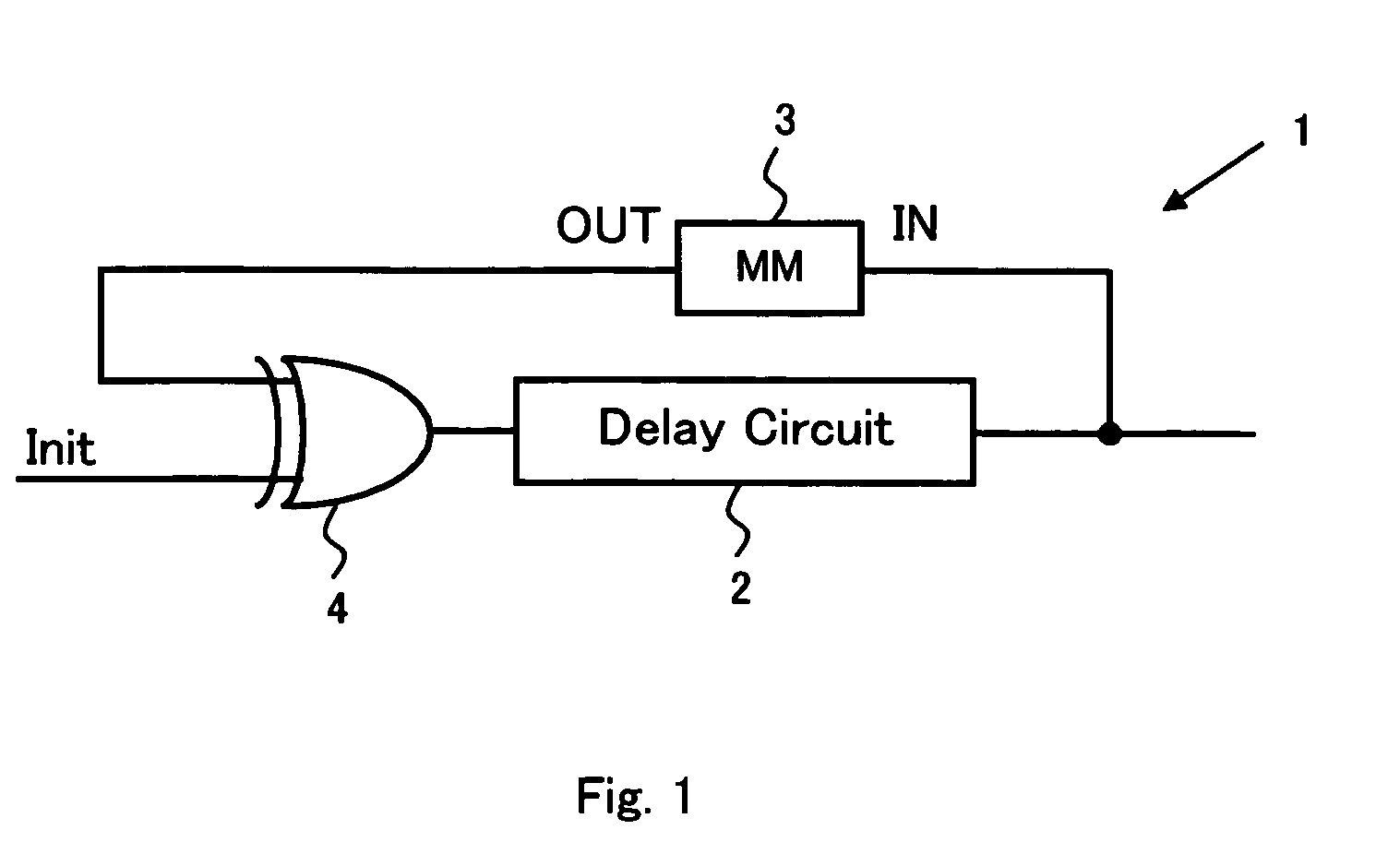
[0200]FIG. 1 is a block diagram showing a configuration example of a ring oscillation circuit 1 due to a positive feedback according to the present invention. As shown in FIG. 1, the ring oscillation circuit 1 is configured by a positive feedback loop to make the circuit of a delay circuit 2, a monostable multivibrator 3, and an oscillation starting circuit 4. According to the configuration example shown in FIG. 1, the output of the delay circuit 2 is connected to the input of the monostable multivibrator 3, and the output of the monostable multivibrator 3 is connected to the input of the delay circuit 2 via the oscillation starting circuit 4. Any circuit configuration of the circuit delay circuit 2 may be allowed if this circuit generates a signal delay between an input terminal and an output terminal. Particularly, the number of inputs and the number of outputs may be plural. A condition to configure a positive feedback loop is to provide a phase relationship of signals between th...

second embodiment

[0212]Next, a ring oscillation circuit using a monostable multivibrator for outputting a falling pulse in response to a falling edge of an input signal will be described. FIG. 10 shows a ring oscillation circuit 11 using a monostable multivibrator 13, which is operated in response to the falling edge. The ring oscillation circuit 11 is configured by a positive feedback loop making the circuit of a delay circuit 12, the monostable multivibrator 13, and an oscillation starting circuit 14. The circuit configuration itself is the same as the circuit configuration shown in FIG. 1, so that the explanation overlapping between them is herein omitted.

[0213]FIG. 11 shows an example of the circuit operation of the monostable multivibrator 13. In the operation example shown in FIG. 11, in response to a falling edge of the input signal, a falling pulse with a pulse width for a predetermined time period, which is specific to a circuit, is outputted.

[0214]FIG. 12 shows a circuit example of a monos...

third embodiment

[0222]Next, a testing circuit according to the present invention for evaluating a timing accuracy of a clock signal will be described. The testing circuit according to the present invention serves to measure the timing accuracy by applying a ring oscillation circuit due to a positive feedback according to the present invention, which is explained with reference to the first or the second embodiment.

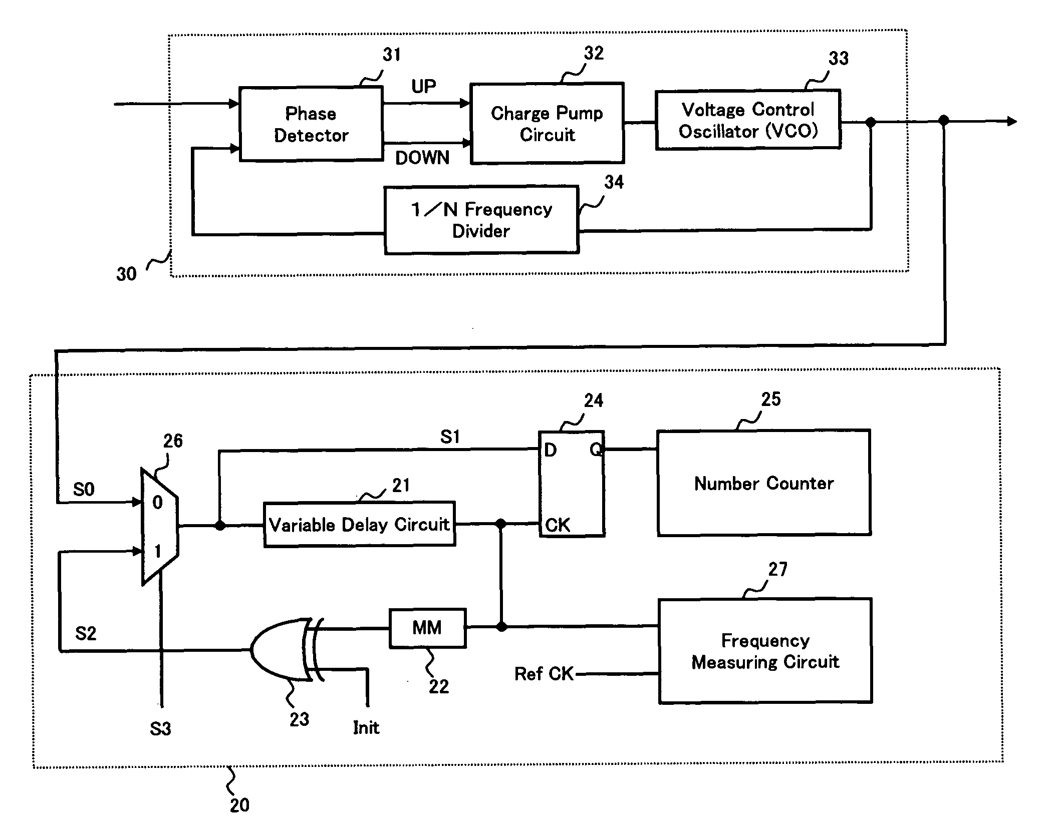
[0223]FIG. 18 is a block diagram showing a circuit configuration of a testing circuit 20 according to the present invention and a circuit configuration when a clock generating circuit 30 for generating a clock signal S0, which is an evaluation object by the testing circuit 20, is configured by a PLL circuit. According to the present embodiment, the case such that the testing circuit 20 and the clock generating circuit 30 are formed on the same semiconductor substrate to be incorporated in one LSI chip is supposed.

[0224]As shown in FIG. 18, testing circuit 20 is configured by a variable de...


PUM


Abstract

A ring oscillation circuit, which can operate the ring oscillation due to a positive feedback stably and continuously, is provided and it is applied to an accurate measurement of delay time and a measurement of timing accuracy in a jitter of a clock signal or the like with a high accuracy. A ring oscillation circuit comprises a delay circuit and a monostable multivibrator. An output of the delay circuit is connected to an input of the monostable multivibrator, an output of the monostable multivibrator is connected to an input of the delay circuit, and the delay circuit and the monostable multivibrator configure a positive feedback loop. An oscillation starting circuit for starting oscillation upon receipt of an input of a trigger pulse for triggering oscillation is provided on the positive feedback loop, or in the inside of the delay circuit or the monostable multivibrator.

Description

CROSS-REFERENCE TO RELATED APPLICATIONS[0001]This application is a National Phase filing under 35 U.S.C. §371 of International Application No. PCT / JP2006 / 323941 filed on Nov. 30, 2006, and which claims priority to Japanese Patent Application No. 2006-025188 filed on Feb. 2, 2006 and Japanese Patent Application No. 2006-220184 filed on Aug. 11, 2006.TECHNICAL FIELD[0002]The present invention relates to a measuring circuit of a delay time and a measuring method, and particularly, the present invention relates to a testing circuit and a testing method for evaluating a timing accuracy of a clock signal, which is generated by a PLL circuit or the like. In addition, the present invention relates to a clock generating circuit such as a PLL circuit equipped with the testing circuit and an image sensor. Further, the present invention relates to a semiconductor integrated circuit, capable of carrying out a delay test according to a scan path method applying a measuring circuit of the delay ti...

Claims


Application Information

Patent Timeline
Patent Type & Authority Patents(United States)
IPC IPC(8): H03K3/03G01R23/175
CPCG01R29/26G01R31/31709G01R31/31725H03K3/0315H03K5/135H03K5/1534
Inventor SHIMAMOTO, YUKIHIRO
Owner SHARP KK
Why Eureka
Try Eureka