Light guide optical system, document illuminating device using same, and image reading apparatus using same

a technology of document illumination and optical system, applied in the direction of optical radiation measurement, lighting and heating apparatus, instruments, etc., can solve the problems of unstable light quantity of cold cathode fluorescent lamps, incongruous illuminance in the main scanning direction, and high cost of us

Active Publication Date: 2010-12-21
CANON KK
View PDF14 Cites 69 Cited by
  • Summary
  • Abstract
  • Description
  • Claims
  • Application Information

AI Technical Summary

Benefits of technology

[0020]According to the present invention, even in a light guide optical system that guides a plurality of light beams emitted from a plurality of point light sources arranged linearly to a predetermined surface, the illumination quality such as illuminance can be uniformized without increasing the diffusion toward the outside of a region to be illuminated.
[0022]Therefore, the illumination quality such as illuminance in a region to be illuminated can be uniformized without increasing the diffusion toward the outside of the region to be illuminated.

Problems solved by technology

Xenon tubes are stable in light quantity and are therefore widely used by apparatuses for business use but are relatively expensive.
However, cold cathode fluorescent lamps are unstable in light quantity.
When a reading surface such as a document surface is directly irradiated with light beams emitted from each of a plurality of point light sources, the illuminance is not uniform in the main scanning direction, and the density of the read image is not uniform.
However, the technology described in Japanese Patent Laid-Open No. 2005- 156600 diffuses light beams randomly and therefore even toward the outside of a predetermined region to be illuminated, and therefore suffers from low light use efficiency of light beams emitted from the light sources.
In addition, a flare phenomenon, in which light beams reflected on a region other than the region to be illuminated fall on the region to be illuminated, occurs and can degrade the quality of the image reading apparatus.
However, increasing the illuminating angle of diffuse light beams diffused by a light diffusing portion causes an absorption reflection phenomenon in the light diffusing portion, and further lowers the light use efficiency.

Method used


Image

  • Light guide optical system, document illuminating device using same, and image reading apparatus using same
  • Light guide optical system, document illuminating device using same, and image reading apparatus using same
  • Light guide optical system, document illuminating device using same, and image reading apparatus using same

Examples


Embodiment Construction

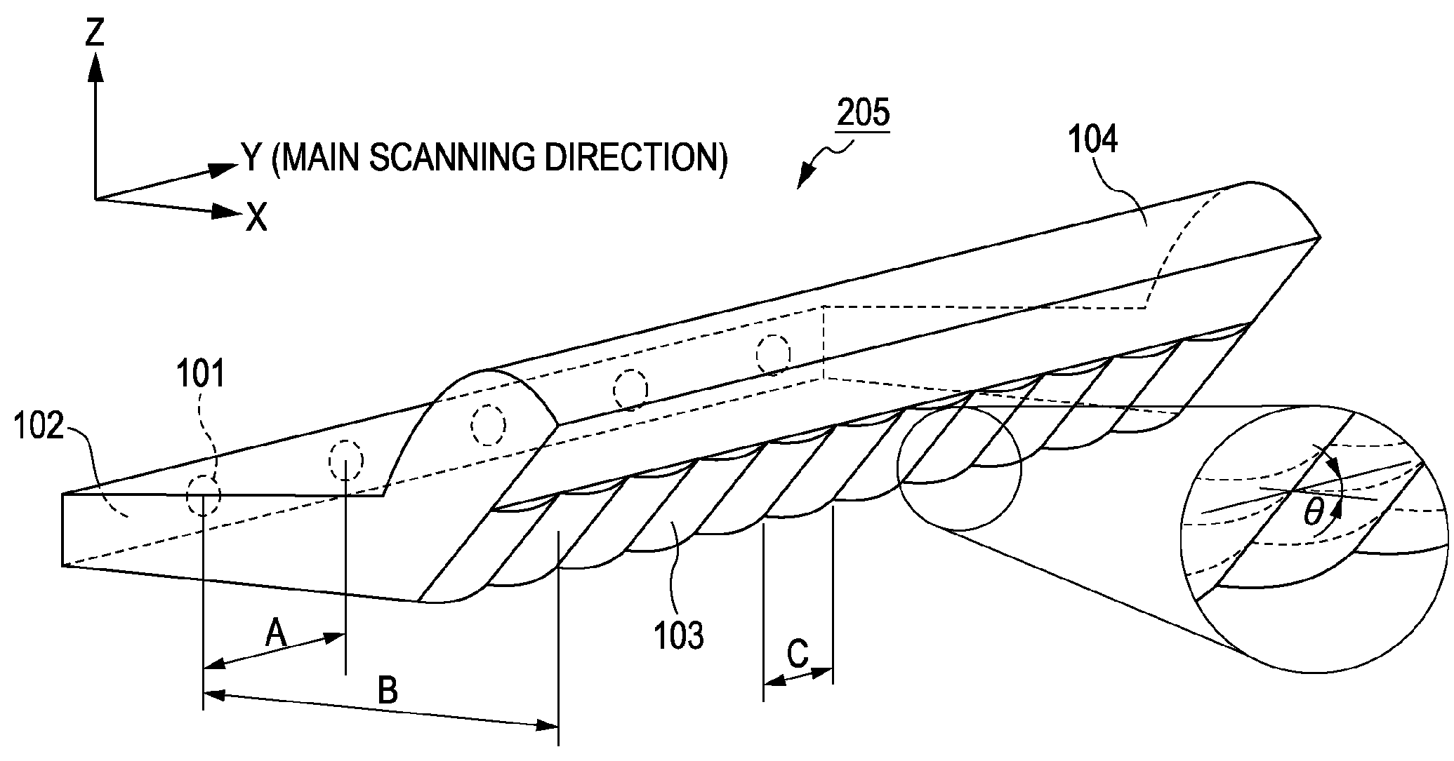
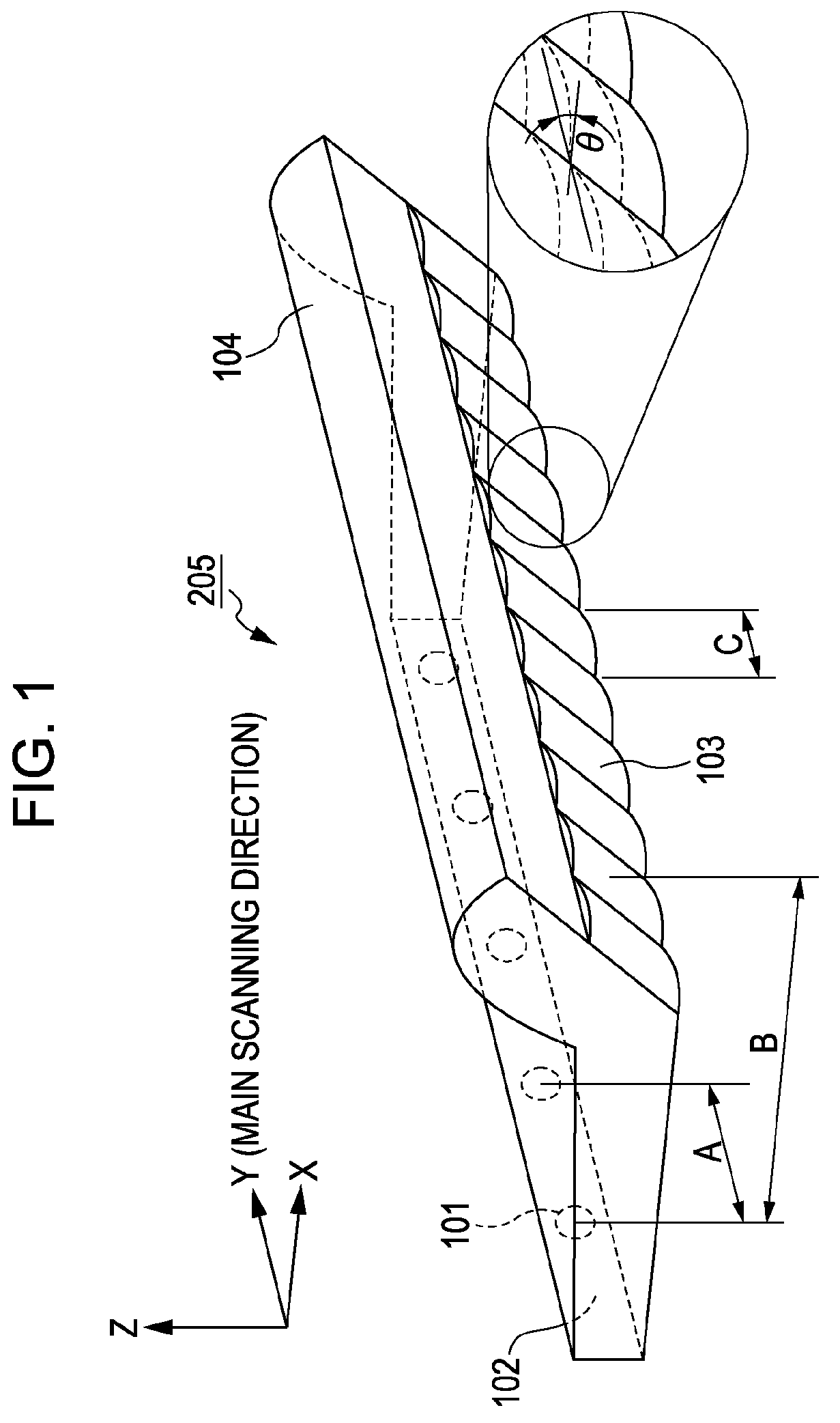
[0029]A document illuminating device 205 of the present invention will be described with reference to FIGS. 1 to 4.

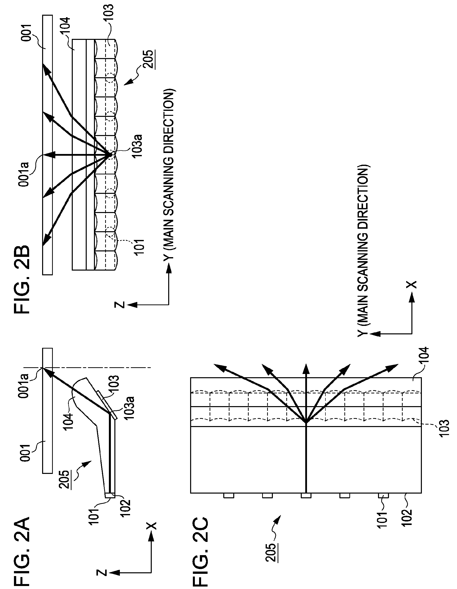
[0030]In FIGS. 1, 2B, and 2C, the direction Y is an arrangement direction in which a plurality of LEDs (light emitting diodes) 101 are arranged linearly, and will be referred to as main scanning direction.

[0031]In FIGS. 1, 2A, and 2C, the X direction is a direction in which a carriage 004 (illustrated in FIG. 4) moves relative to a document table glass 001, and will be referred to as subscanning direction. A direction perpendicular to the X and Y directions will be referred to as Z direction.

[0032]FIG. 1 is a perspective view of a light guide optical system (light guide member) of the present invention. The plurality of LEDs (light emitting diodes) 101 arranged in the main scanning direction are disposed on an entrance surface 102 of the light guide optical system.

[0033]A plurality of light beams emitted from the plurality of point light sources (LEDs) 101 are totally r...


PUM


Abstract

A light guide optical system guides a plurality of light beams emitted from a plurality of point light sources arranged linearly to a predetermined surface. The light guide optical system has a plurality of optical surfaces arranged periodically in the arrangement direction of the plurality of point light sources. Each of the plurality of optical surfaces has power in the arrangement direction of the plurality of point light sources.

Description

BACKGROUND OF THE INVENTION[0001]1. Field of the Invention[0002]The present invention relates to a light guide optical system, a document illuminating device using the same, and an image reading apparatus using the same. More specifically, the present invention relates to an image reading apparatus that illuminates a document surface and performs image reading in a line-sequential manner, for example, an image scanner, a copying machine, or a facsimile.[0003]2. Description of the Related Art[0004]In general, a document illuminating device used by an image reading apparatus that illuminates a document surface and performs image reading in a line-sequential manner, for example, an image scanner, a copying machine, or a facsimile illuminates a document surface using a tubular (linear) light source such as a fluorescent lamp.[0005]FIG. 5 is a sectional view of a main portion of a typical image reading apparatus. Illuminating light emitted from a tubular light source 005 illuminates a do...

Claims


Application Information

Patent Timeline
Patent Type & Authority Patents(United States)
IPC IPC(8): H04N1/04
CPCH04N1/02815H04N1/02835H04N1/02885
Inventor HAYASHIDE, TADAOSUGIYAMA, TAKAYUKI
Owner CANON KK
Why Eureka
Try Eureka