
System and method for optimization of a radiation therapy plan in the presence of motion

a radiation therapy and motion optimization technology, applied in the field of radiation therapy planning, can solve the problems of not receiving the correct dosage for the target area or parts of the patient area, and neither the location of the patient nor the target area is usually static,

Active Publication Date: 2010-12-21
WISCONSIN ALUMNI RES FOUND
View PDF58 Cites 13 Cited by
  • Summary
  • Abstract
  • Description
  • Claims
  • Application Information

AI Technical Summary

Benefits of technology

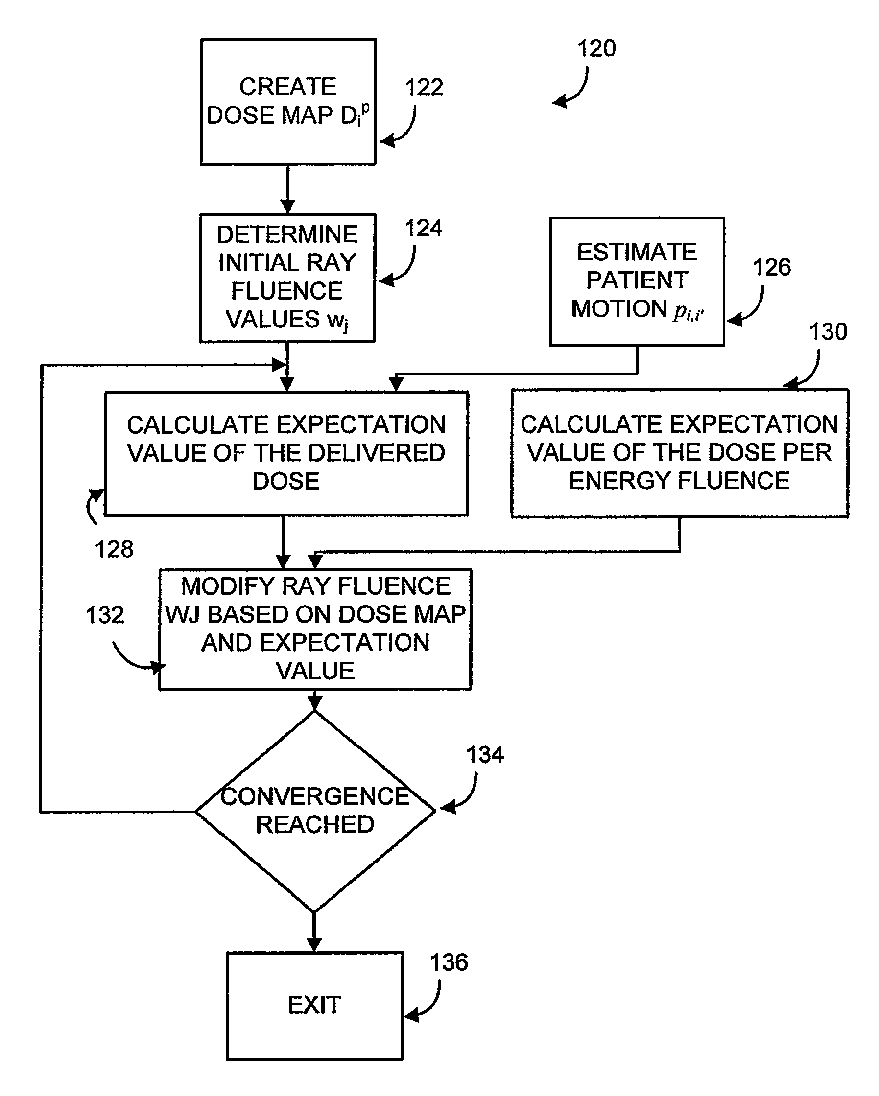
The patent describes a computer-implemented method for optimizing a radiation treatment plan for a radiotherapy machine that provides independently controlled radiation. The method takes into account the effects of patient motion and uses a probability distribution function to quantitatively express patient motion. The method involves identifying a prescribed total dose and assigning a fluence value to each ray of radiation based on an iterative function. The expected dose per energy fluence is then calculated, and an actual total dose is produced for each voxel in the treatment area. The method can be implemented using a computer system and a shutter system to attenuate the radiation. The technical effect of the patent is to provide a more accurate and effective radiation treatment plan for patients with moving tumors or sensitive areas.

Problems solved by technology

However, neither the location of the patient nor the location a target area is usually static.
Accordingly, even considering the accuracy of the IMRT method, a target area or portions of a patient area may not receive the correct dosage designated by a treatment plan.

Method used


Image

  • System and method for optimization of a radiation therapy plan in the presence of motion
  • System and method for optimization of a radiation therapy plan in the presence of motion
  • System and method for optimization of a radiation therapy plan in the presence of motion

Examples


Embodiment Construction

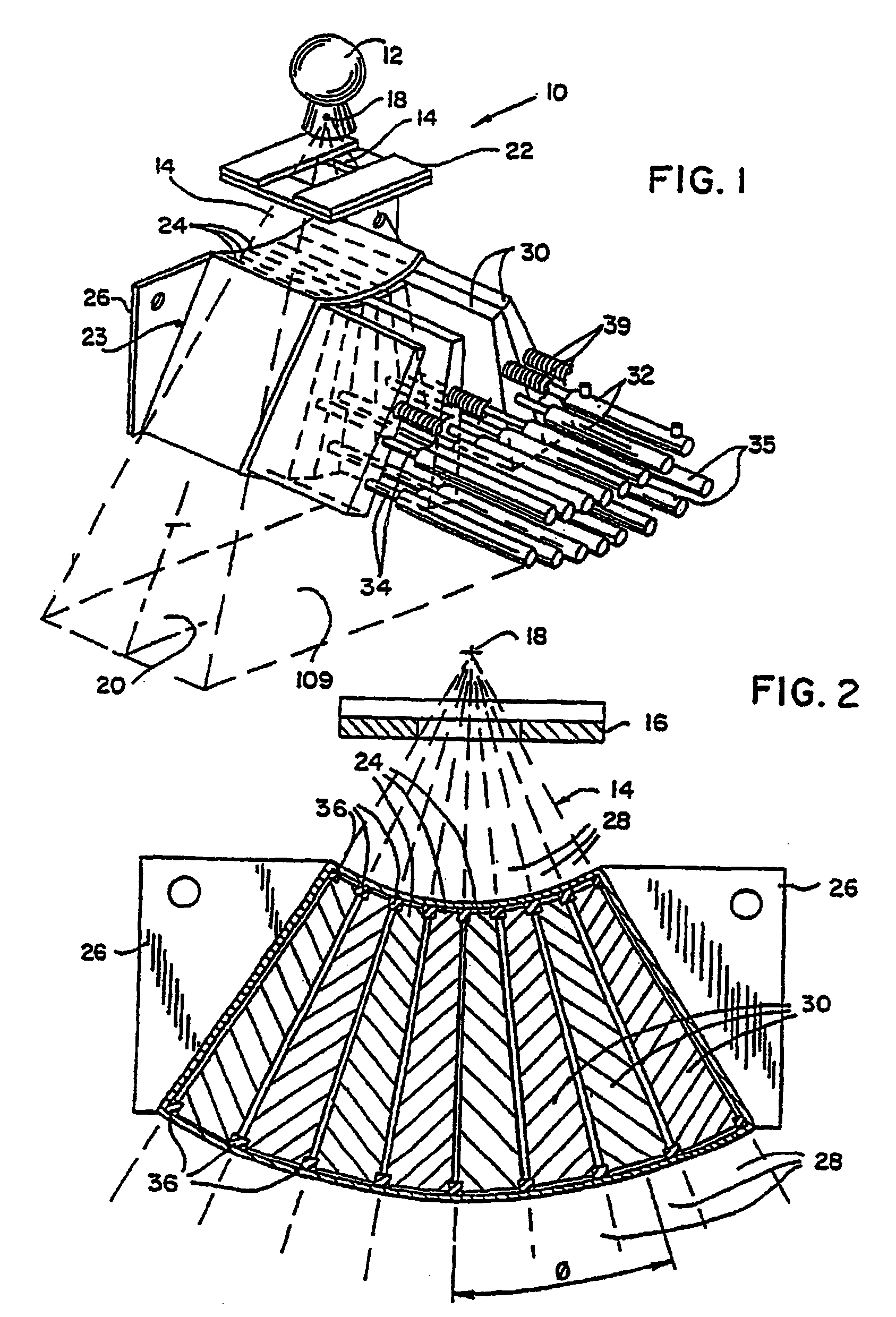
[0024]Referring to FIG. 1, such a radiation therapy machine 10 includes a radiation source 12 producing a generally conical radiation beam 14′ emanating from a focal spot 18 and directed toward a patient 17 (not shown in FIG. 1). The conical radiation beam 14′ is collimated by a rectangular opaque mask 16 constructed of a set of rectangular shutter system blades to form a generally planar radiation fan beam 14 centered about a radiation fan beam plane 20. Whereas the present application describes a multi-leaf collimator-type radiation therapy machine system, the system and method described herein may be used with any therapy machine configured to perform intensity modulated radiation therapy.

[0025]A shutter system 22 is centered in the radiation fan beam 14 and about the radiation fan beam plane 20 prior to the radiation beam being received by the patient 17, and includes a plurality of adjacent trapezoidal leaves 30 which together form an arc of constant radius about the focal spot...


PUM


Abstract

A computer-implemented method for optimizing a radiation treatment plan for a radiotherapy machine providing independently controlled radiation along a plurality of rays j directed toward a patient and configured to account for the effects of patient motion. The method includes generating a probability distribution function quantitatively expressing patient motion, identifying a prescribed total dose Dip at the voxels i in a treatment area, assigning a fluence value wj for each ray j based on an iterative function, calculating an actual total dose Did produced each voxel i within the assigned fluence values and calculating an expectation value of the dose per energy fluence, dij based on the actual total dose Did and the probability distribution function.

Description

CROSS-REFERENCE TO RELATED APPLICATIONS[0001]This application claims the benefit of U.S. Provisional Application 60 / 891,859, filed Feb. 27, 2007, and PCT Application PCT / US2008 / 055147, filed Feb. 27, 2008, the disclosures of which are incorporated herein by reference.STATEMENT REGARDING FEDERALLY SPONSORED RESEARCH OR DEVELOPMENT[0002]This invention was made with United States government support awarded by the following agency: NIH CA088960. The United States government has certain rights in this invention.BACKGROUND OF THE INVENTION[0003]The present invention relates generally to radiation therapy planning for the treatment of tumors and is suitable for radiation therapy machines providing independent intensity modulated narrow beams of radiation. More specifically, the present invention relates to a system and method for generating intensity maps for intensity modulated therapy (IMRT) in which the effects of patient motion are taken into account.[0004]Radiation therapy involves th...

Claims


Application Information

Patent Timeline
Patent Type & Authority Patents(United States)
IPC IPC(8): A61N5/10
CPCA61N5/103A61N5/1037A61N5/1042A61N2005/1041G21K1/046
Inventor FLYNN, RYAN T.MACKIE, THOMAS R.
Owner WISCONSIN ALUMNI RES FOUND
Learn More