Vestibular system stimulation apparatus

a technology of vestibular system and apparatus, which is applied in the direction of artificial respiration, therapy, physical therapy, etc., can solve the problems of involuntary twitching and auditory perception, vertigo, and dizziness of patients, respectively

Active Publication Date: 2010-12-21
KONINKLIJKE PHILIPS ELECTRONICS NV
View PDF22 Cites 57 Cited by
  • Summary
  • Abstract
  • Description
  • Claims
  • Application Information

AI Technical Summary

Benefits of technology

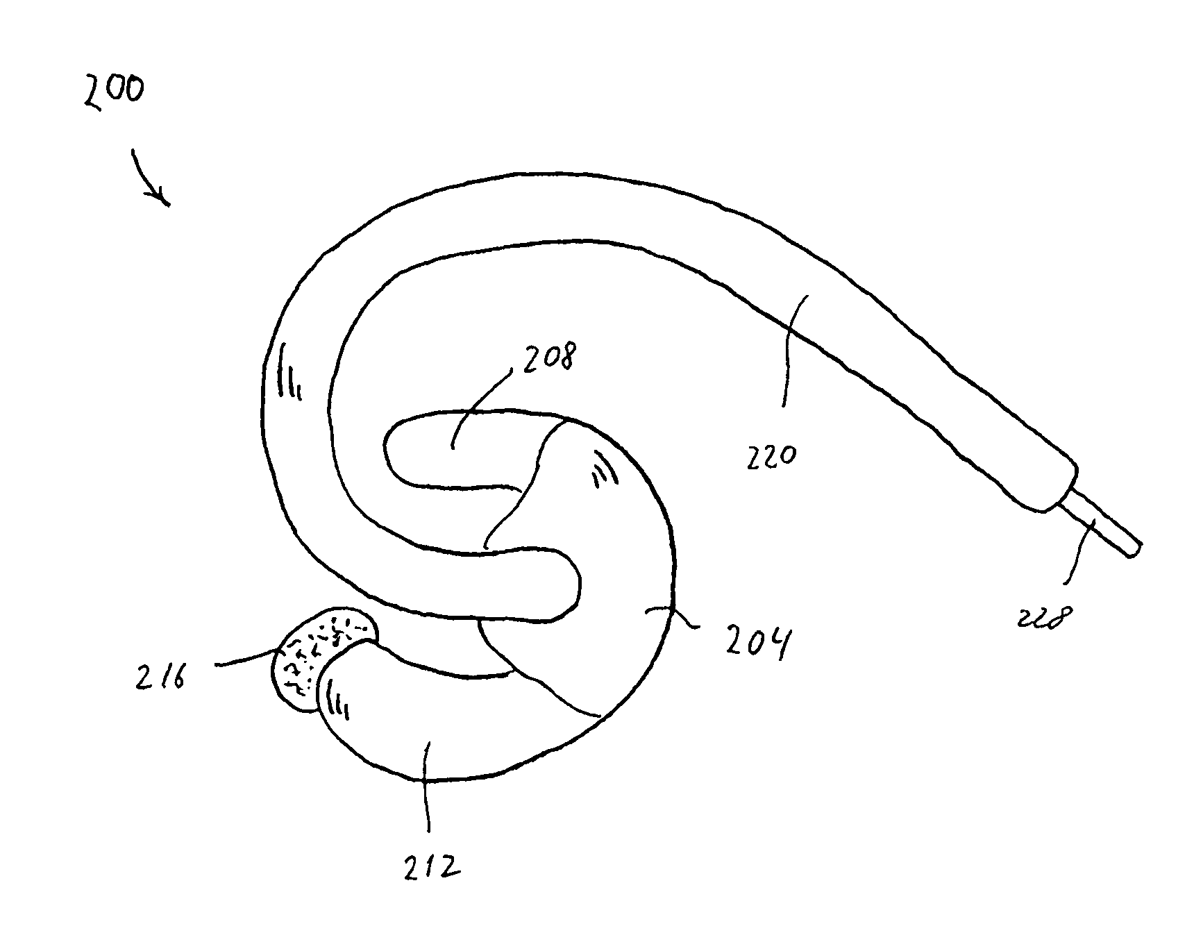
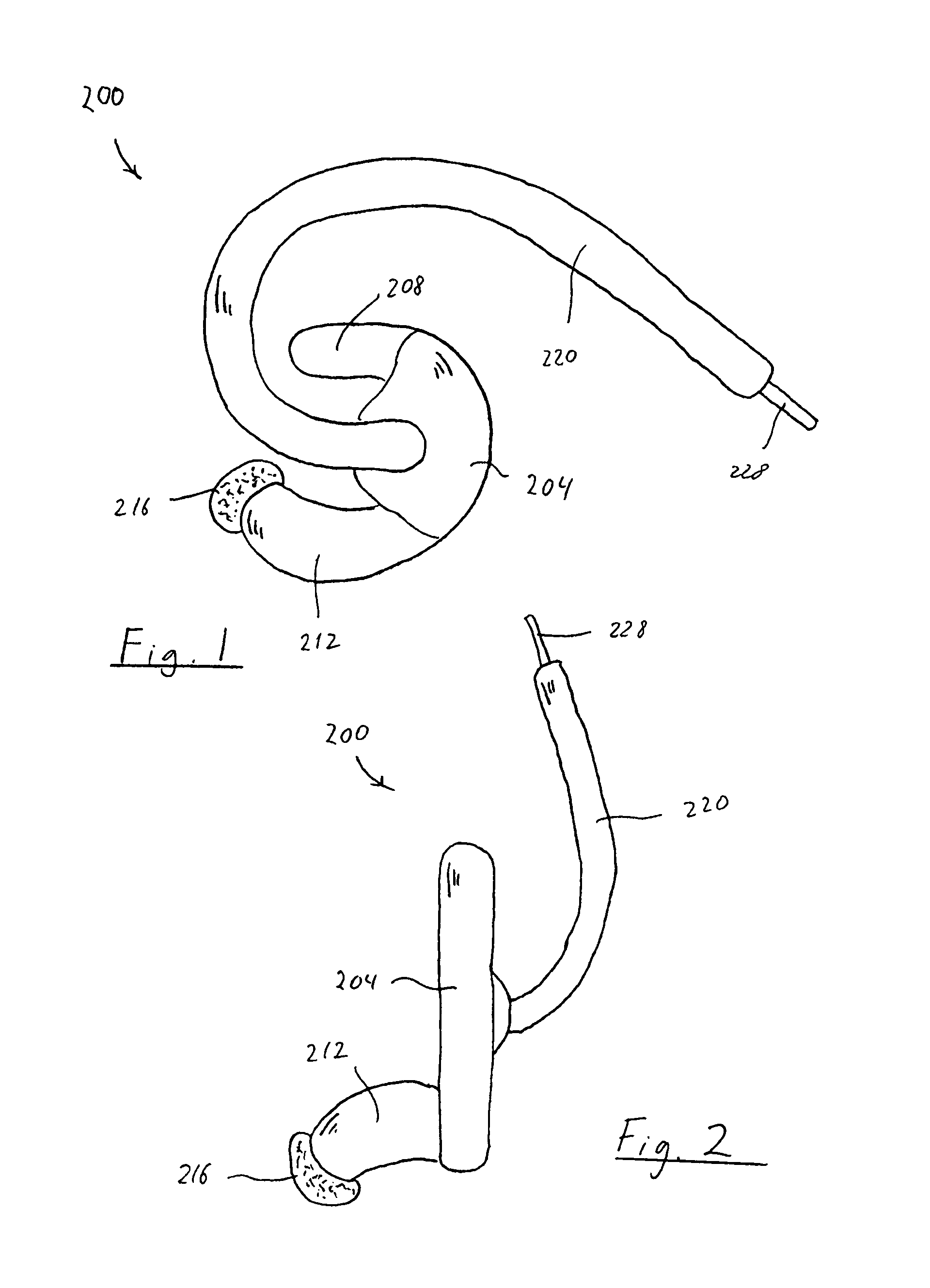
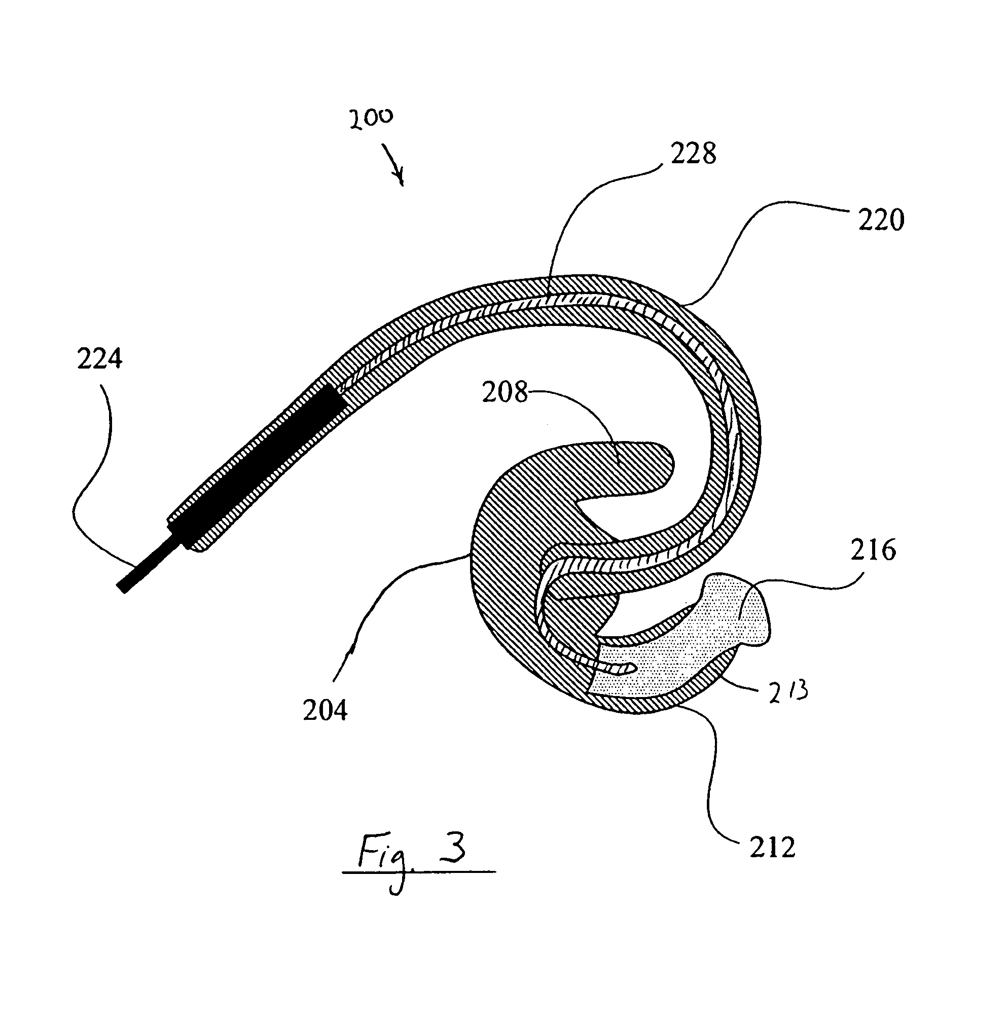
[0011]In a further exemplary embodiment of the present invention, the deformable material is a porous material and an electrolytic substance is disposed in at least a portion of the porous material. The present invention also contemplates providing a reservoir of electrolytic solution that is integral to or associated with the structure that supports the stimulating electrode. The present invention also contemplates that the stimulating electrode is a porous conductive material, eliminating the need for an electrolytic substance.

Problems solved by technology

Disorders of the vestibular system may result in physiological disorders such as dizziness, vertigo, and nausea, with symptoms ranging in severity from mild to completely debilitating.
Stimulation of the vestibular system via a surface electrode often causes non-specific activation of nerves and muscles that result in unpleasant experiences for the patient.
For example, surface electrode stimulation of the vestibular system may result in non-specific activation of facial muscles and / or the auditory aspect of the eighth cranial nerve, causing involuntary twitches and auditory perceptions, respectively.
While direct electrode stimulation of the semi-circular canals is specific, the placement of an electrode through the tympanic membrane and / or within the inner ear can be quite unpleasant for the patient, and also presents an opportunity for infection of or physical damage to the inner ear, tympanic membrane, or other components of the ear.

Method used


Image

  • Vestibular system stimulation apparatus
  • Vestibular system stimulation apparatus
  • Vestibular system stimulation apparatus

Examples


fifth embodiment

[0054]FIG. 7 illustrates a fifth embodiment for an electrode assembly 300 according to the principles of the present invention that accomplishes this function. In this embodiment, a bladder 302 is provided in body member 304 that stores the electrolytic substance. A channel 306 is provided from the bladder to stimulating electrode 216. The user dispenses the electrolytic substance stored in the bladder into the porous material by squeezing the bladder causing the electrolytic substance to be injected into the porous material. While the bladder is shown provided within the body member, the present invention also contemplates providing the bladder in first protrusion 208, second protrusion 212, or any combination thereof.

[0055]The present invention further contemplates removing the bladder from the electrode assembly but leaving an electrolytic substance filling channel defined from a portion of the electrode assembly to the porous material. A filling port (not shown) would have to be...

sixth embodiment

[0056]FIG. 8 is a cross-sectional view of a vestibular stimulation electrode assembly 320 according to the principles of the present invention. In this embodiment, body member 322, first protrusion 324, and second protrusion 326 are formed from a single piece of porous material 328 that also forms stimulating electrode 330. That is, a hot molding method is used to form a cured hydrophilic foam, which serves as the stimulating electrode, into the shape shown in the FIG. 8. The foam also defines the general overall shape for the entire electrode assembly. A lead wire 332 is fixed to the stimulating electrode. The body member, the first protrusion, and the second protrusion are formed by applying a coating of material to the outer surface of the porous material using any conventional process, such as a spraying or dipping type process. In a preferred embodiment, this outer coating of material is formed from a soft rubber, is an electrical insulator, and is water-proof.

[0057]The area of...

seventh embodiment

[0060]FIGS. 9A and 9B illustrate a seventh embodiment for an electrode assembly 350 according to the principles of the present invention. A prominent feature of this embodiment is the relatively large kidney shape for body member 352. A first arm 354 is provided at one end of the C-shaped body member, and a second arm 356 is provided at an opposite end of the body member. Stimulating electrode 358 is provided at the end of second arm 356.

[0061]The body member is preferably defined by a first limb 360 and a second limb 362 with an opening 364 defined between these two members. First limb 360 is preferably formed from a thin membrane, so that it easily deforms around the cartilage of the ear, namely around the crux, which separates the concha into upper and lower parts. When properly worn in the ear, first arm 354 fits in the cymba conchae, and the second arm 356 fits in the cavum conchae. Second limb 362 provides the strength to maintain the structure in the ear.

[0062]A distal end po...


PUM


Abstract

Apparatus for the non-invasive and specific activation of the vestibular system in a patient. Preferred embodiments of the present invention allow for the placement of a stimulating electrode in the ear canal while providing a firm and comfortable coupling with the patient. The stimulating electrode is a deformable material that contacts the skin in the ear canal. A stimulating device operates in cooperation with the stimulating electrode to generate a stimulation waveform for the stimulation of the vestibular system.

Description

CROSS-REFERENCE TO RELATED APPLICATIONS[0001]This application claims priority under 35 U.S.C. §119(e) from provisional U.S. patent application No. 60 / 642,367 filed Jan. 7, 2005, the contents of which are incorporated herein by reference.BACKGROUND OF THE INVENTION[0002]1. Field of the Invention[0003]The present invention relates to an apparatus for stimulating the vestibular system, and, in particular, to a non-invasive stimulation electrode assembly having a portion that fits within the ear canal to stimulate the vestibular system and to a system using such an electrode assembly.[0004]2. Description of the Related Art[0005]The vestibular system is responsible for the detection of the position and motion of the head in space. The semicircular canals, which are located in the inner ear, are the sensory organs of the vestibular system, and collect head position and motion information and transmit it to the central nervous system via the eighth cranial nerve. Disorders of the vestibula...

Claims


Application Information

Patent Timeline
Patent Type & Authority Patents(United States)
IPC IPC(8): A61N1/36
CPCA61N1/0496A61N1/0541A61N1/36032A61N1/36014A61N1/0526A61N1/36036
Inventor PAUL, ZACHARYLATTNER, STEFANIEBLAKE, STEFANIDA K.DEVINNEY, PATRICKDIMATTEO, MARKRADNEY, STEVEN B.HO, PETER CHI FAIGIOVANNELLI, BENJAMIN A.CESSNA, MICHAELCOLBAUGH, MICHAEL E.
Owner KONINKLIJKE PHILIPS ELECTRONICS NV
Why Eureka
Try Eureka