
Pressure sensor having a diaphragm having a pressure-receiving portion receiving a pressure and a thick portion adjacent to the pressure-receiving portion

a diaphragm and pressure sensor technology, applied in the direction of fluid pressure measurement by mechanical elements, fluid pressure measurement using elastically deformable gauges, instruments, etc., can solve the problems of reducing narrowing the variable oscillation frequency range, and deteriorating the resolution power of pressure measurement, so as to increase the breaking limit of the pressure sensitive element, widen the working pressure range, and prolong the life

Inactive Publication Date: 2010-12-28
SEIKO EPSON CORP
View PDF9 Cites 1 Cited by
  • Summary
  • Abstract
  • Description
  • Claims
  • Application Information

AI Technical Summary

Benefits of technology

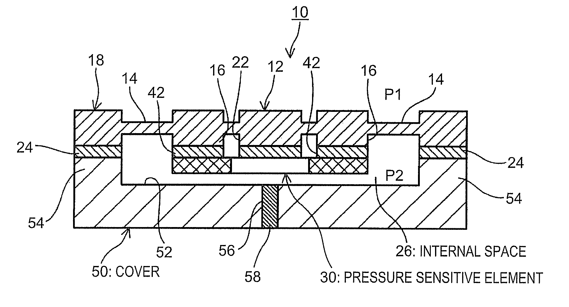
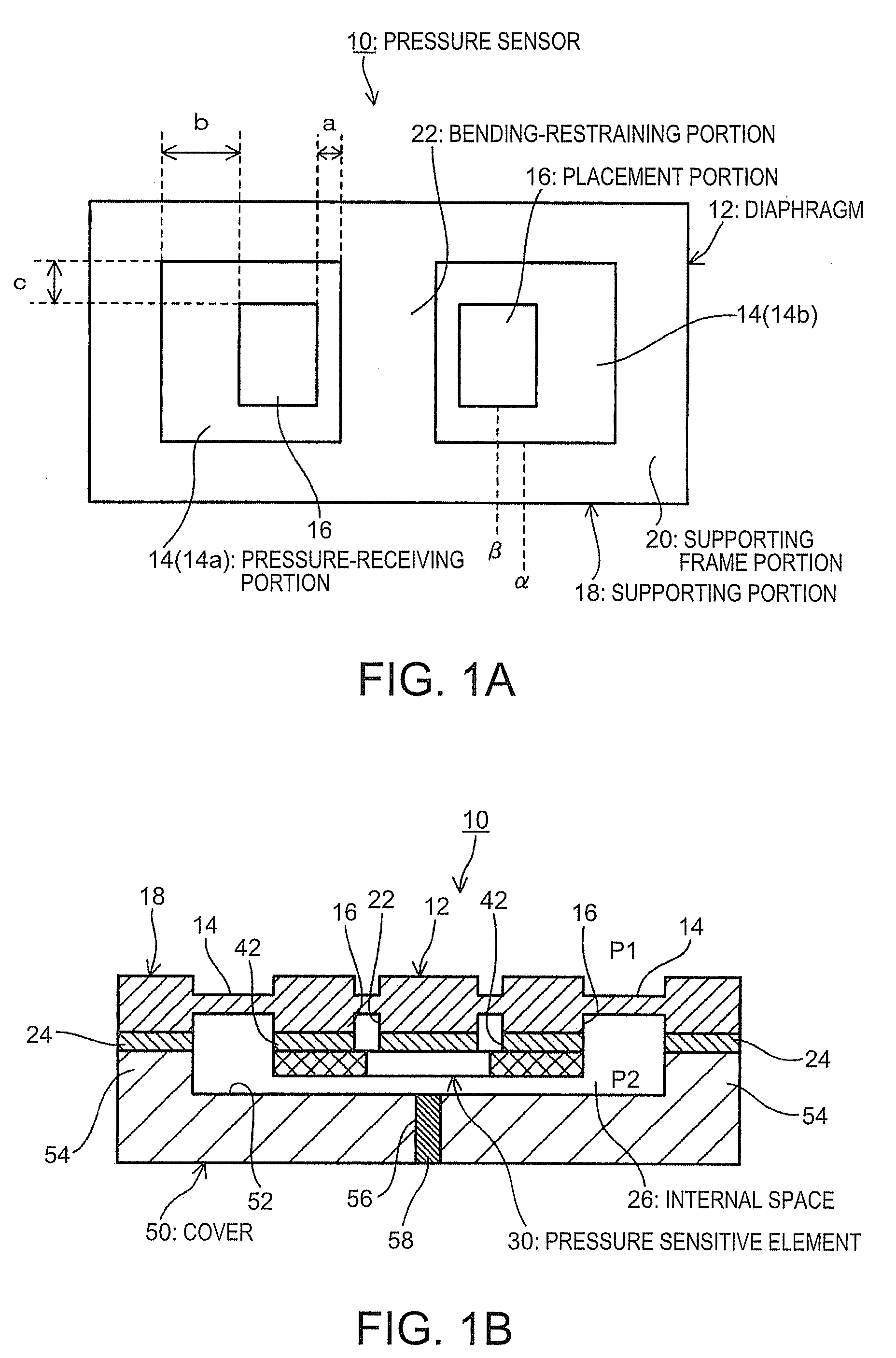
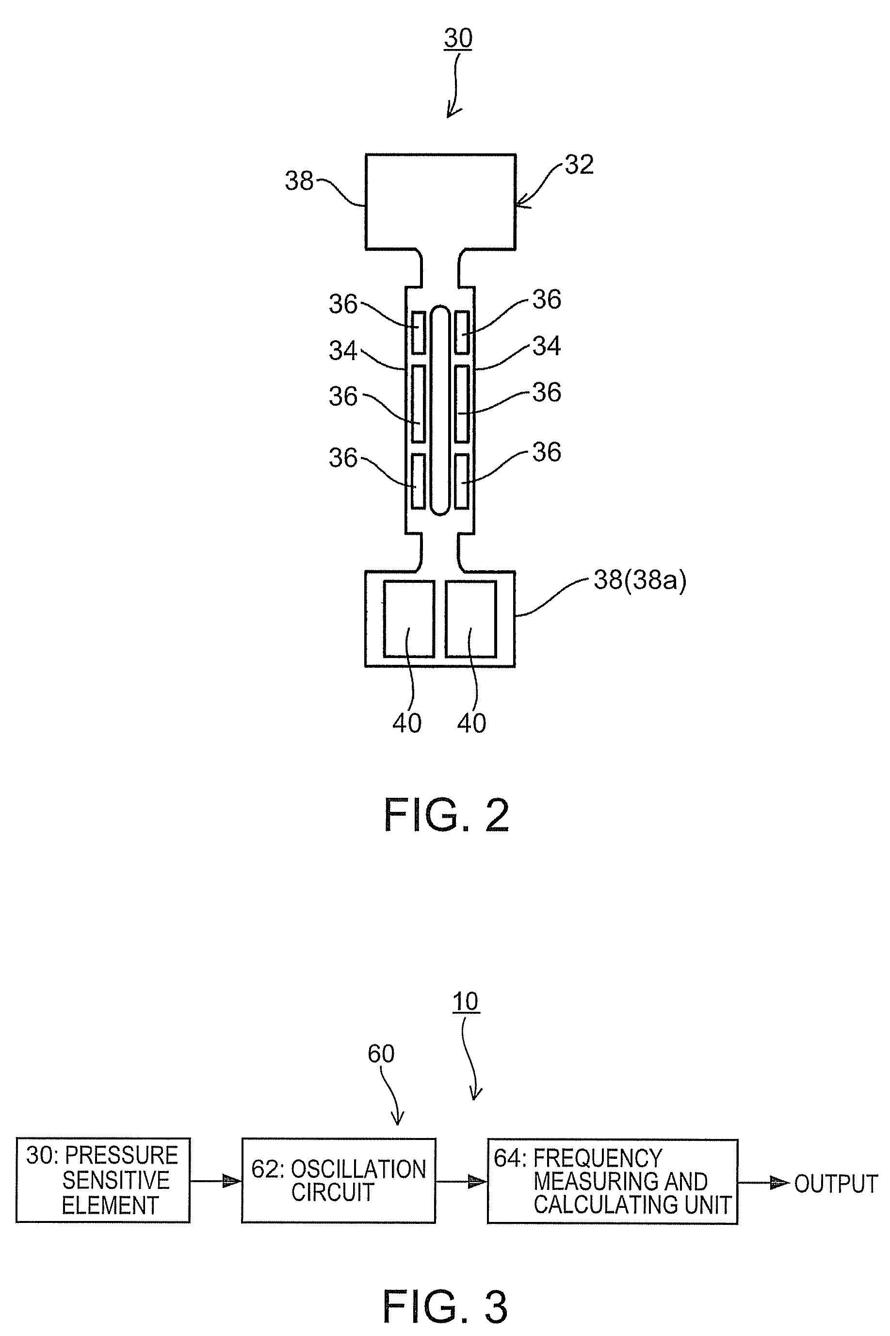
The invention provides a pressure sensor with a long lifespan and a wider working pressure range. The pressure sensor includes a diaphragm with a pressure-receiving portion and a thick portion, and a pressure sensitive element bonded to the pressure-receiving portion. The pressure sensitive element receives a compressive stress from the one side, increasing its breaking limit. The sensor also includes a supporting portion and a bending-restraining portion, which helps to widen the working pressure range. The pressure sensor can be used in an airtight space and includes an oscillation circuit and a frequency measuring and calculating unit for obtaining pressure values.

Problems solved by technology

That is, when a tensile stress or a compressive stress is applied to the double-ended tuning fork resonator element, the breaking limit becomes larger when a compressive stress is applied rather than when a tensile stress is applied.
Thus, if the breaking limit is small, a large stress cannot be applied, resulting in a variable oscillation frequency range being narrowed.
As a result, the resolving power of a pressure measurement is deteriorated.
In addition, the double-ended tuning fork resonator element receives a large mechanical stress when a tensile stress is applied to it.
This stress increases a possibility of the double-ended tuning fork resonator element being broken and may arise a problem in that electrode patterns provided to the double-ended tuning fork resonator element are broken.
As a result, the pressure sensor lasts short.

Method used


Image

  • Pressure sensor having a diaphragm having a pressure-receiving portion receiving a pressure and a thick portion adjacent to the pressure-receiving portion
  • Pressure sensor having a diaphragm having a pressure-receiving portion receiving a pressure and a thick portion adjacent to the pressure-receiving portion
  • Pressure sensor having a diaphragm having a pressure-receiving portion receiving a pressure and a thick portion adjacent to the pressure-receiving portion

Examples


first embodiment

[0062]The pressure sensitive element 30 used for the pressure sensor 10 has a central portion thicker than its both ends. That is, the double-ended tuning fork resonator element 32 used as the pressure sensitive element 30 has the base 38 having a thickness thicker than that of the resonating arms 34 allows the pressure sensitive element 30 to step over the bending-restraining portion 22, as shown in FIG. 7B. The pressure sensitive element 30 may be bonded to areas, indicated with broken lines in FIG. 7A, of the pressure-receiving portion 14 with the connecting member 42 so that the bonding position of the pressure sensitive element 30 and the pressure-receiving portion 14 is the same as that of the This structure allows the pressure sensitive element 30 to receive a compressive stress. The cover 50 is bonded to the lower surface of the diaphragm 72 so that the recess 52 faces the diaphragm 72. The internal space 26 formed by the cover 50 and the diaphragm 72 is made into a vacuum ...

fourth embodiment

[0068]A diaphragm 74 of the fourth embodiment includes the supporting portion 18, the pressure-receiving portion 14, and the placement portion 16. The upper surfaces of the supporting portion 18 and the pressure-receiving portion 14 form the same plane. The lower surfaces of the supporting portion 18 and the placement portion 16 are protruded downwardly from the lower surface of the pressure-receiving portion 14. The under surface of the supporting portion 18 is protruded downwardly from the lower surface of the placement portion 16. The supporting portion 18 includes the supporting frame portion 20 and a bending-restraining portion 76. The bending-restraining portion 76 is disposed between the first pressure-receiving portion 14a and the second pressure-receiving portion 14b. The supporting portion 20 surrounds whole of the first pressure-receiving portion 14a and the second pressure-receiving portion 14b.

[0069]The bending-restraining portion 76 is composed of two portions each pr...

fifth embodiment

[0080]The diaphragm 82 of the fifth embodiment may have its flat upper surface as shown in FIG. 6B. The diaphragm 82 of the embodiment also may not include the placement portion 16 provided to the pressure-receiving portion 14 as shown in FIGS. 7A and 7B.

[0081]A sixth embodiment of the invention is now described. In the embodiments described above, the pressure sensitive element 30 is housed in the internal space 26 formed by the diaphragm and the cover 50. The pressure sensor 10 of the invention, however, may have a three-layer structure in which a pressure sensitive sensor provided with a frame is sandwiched between the diaphragm 12 and the cover 50. The pressure sensor 10 having the three-layer structure will be described in the sixth embodiment. The pressure sensor having the three-layer structure can be applied to the first through third embodiments. The structure will be described in which the pressure sensor 10 of the first embodiment employs the three-layer structure. In the...


PUM

PropertyMeasurementUnit
pressureaaaaaaaaaa
pressure sensitiveaaaaaaaaaa
frequencyaaaaaaaaaa

Abstract

A pressure sensor includes: a diaphragm having a pressure-receiving portion receiving a pressure and a thick portion adjacent to the pressure-receiving portion; and a pressure sensitive element having a first and a second ends facing each other. The pressure sensitive element extends in a direction intersecting the thick portion and the first end of the pressure sensitive element is bonded to a pressure-receiving surface of the pressure-receiving portion, and a central portion of a portion at which the pressure-receiving portion and the first end are bonded is positioned at a side closer to the second end of the pressure sensitive element than a center of the pressure-receiving portion.

Description

BACKGROUND[0001]1. Technical Field[0002]The present invention relates to a diaphragm type pressure sensor.[0003]2. Related Art[0004]Some pressure sensors use a diaphragm. The sensor including a diaphragm (a diaphragm type pressure sensor), which has a pressure-receiving portion bent by a pressure difference applied to both sides thereof, measures a pressure by using a pressure sensitive element detecting the bending.[0005]JP-A-2004-132913 discloses a diaphragm type pressure sensor. The pressure sensor disclosed in JP-A-2004-132913 can measure a relative pressure as well as an absolute pressure. The pressure sensor includes quartz crystal diaphragms at a base side and a lid side. Each diaphragm has a recess. The pressure sensor has an internal space formed by facing the recess of each quartz crystal diaphragm and bonding the diaphragms in a laminated direction. A double-ended tuning fork resonator is disposed in the recess of the quartz crystal diaphragm at the base side in the inter...

Claims


Application Information

Patent Timeline
Patent Type & Authority Patents(United States)
IPC IPC(8): G01L9/04
CPCG01L9/0016G01L9/0022
Inventor SAKURAI, TOSHINOBU
Owner SEIKO EPSON CORP
Learn More