Pressure accumulator, especially pulsation damper

a technology of pulsation damper and accumulator, which is applied in the direction of actuator accumulator, accumulator installation, pipe element, etc., can solve the problems of comparatively poor response behavior in operation, increased spring stiffness, and damage to the bellows, and achieves reliable operation and large damping

Active Publication Date: 2010-12-28
HYDAC TECH GMBH
View PDF29 Cites 5 Cited by
  • Summary
  • Abstract
  • Description
  • Claims
  • Application Information

AI Technical Summary

Benefits of technology

[0006]An object of the present invention is to provide an improved pressure accumulator while maintaining the prior advantages, such that in a very small installation space a large measure of damping is achieved with respect to the pulsations of a hydraulic fluid including fuel such as d

Problems solved by technology

However, there is the danger of damage to the bellows in states with an overpressure prevailing on the oil side or in the absence of the prefill pressure on the gas side.
Disadvantageously for this reason the spring stiffness is greatly increased.
This increased spring stiffness leads to a comparatively poor response behavior in operation.
Multilayer bellows lead to increased weight and higher costs.
In spite of this circumstance and in spite of the existing very small “dead volume” between the troug

Method used


Image

  • Pressure accumulator, especially pulsation damper
  • Pressure accumulator, especially pulsation damper

Examples


Embodiment Construction

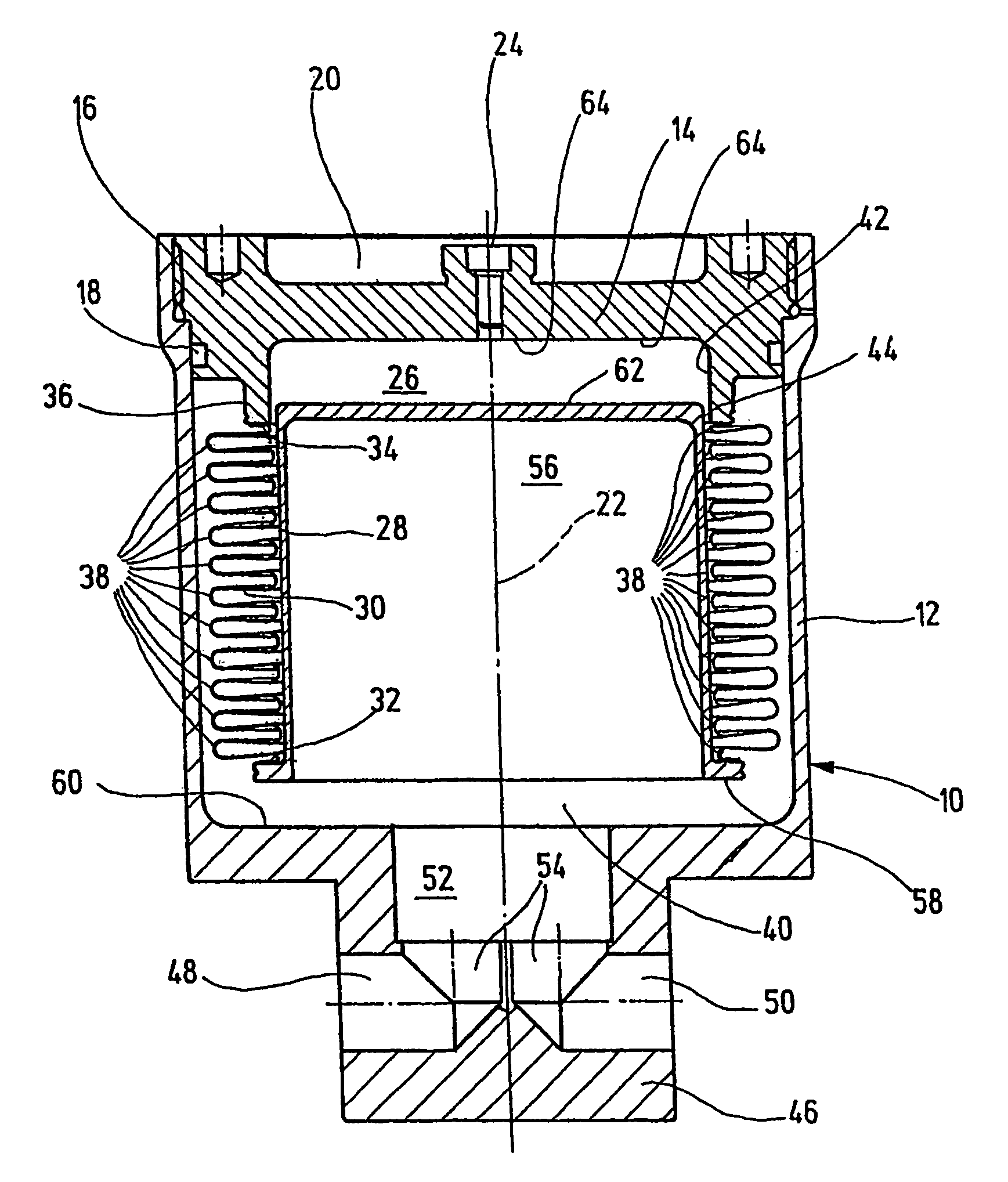
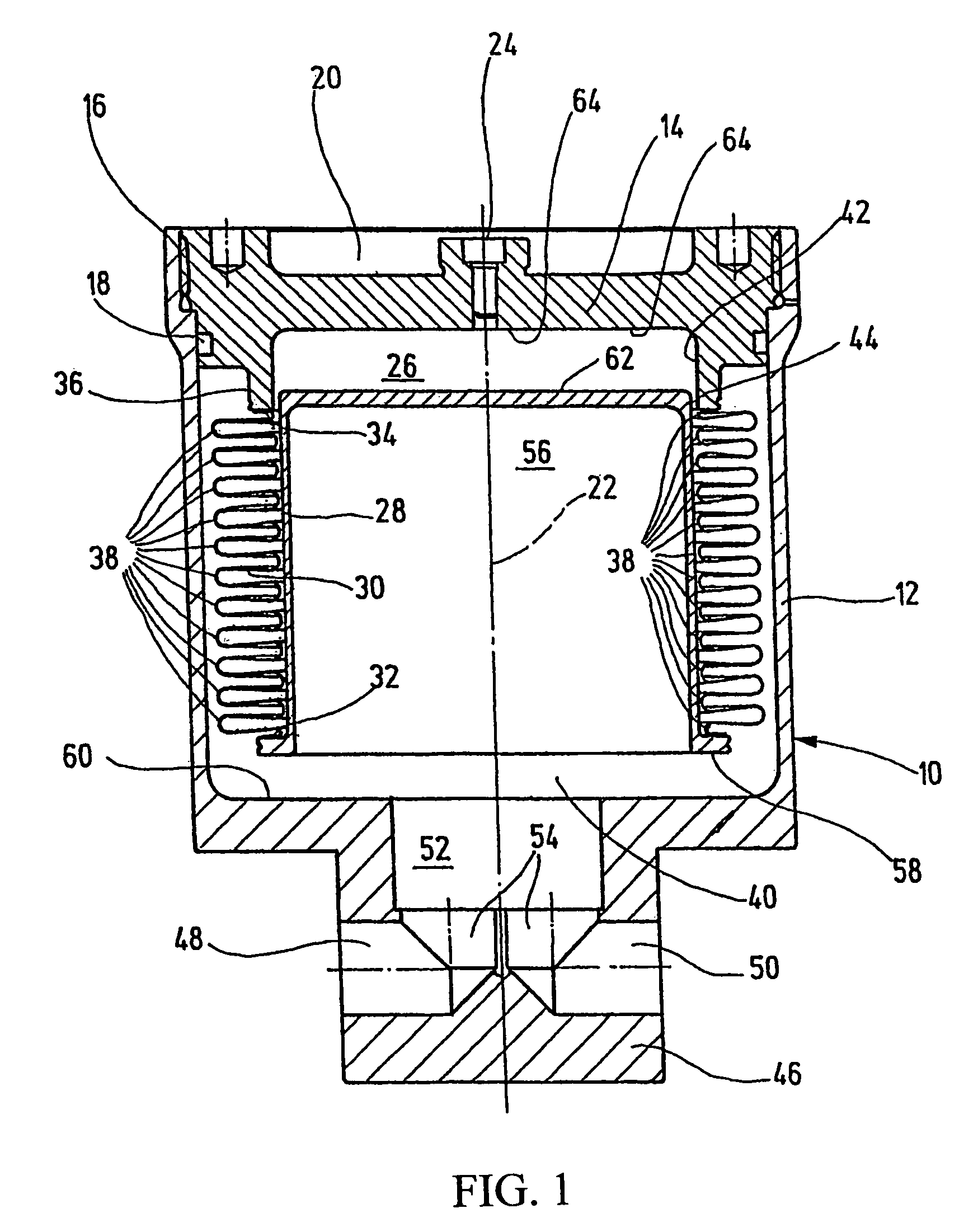
[0014]The illustrated exemplary embodiment of a pressure accumulator is intended especially for use in fuel and heavy oil systems to damp and smooth pressure surges of the operating medium. In the area of fuels, especially diesel fuel or the like is meant. The pressure accumulator could also be used in electrohydraulic braking systems, for example in vehicle construction. The illustrated pressure accumulator has a pressure accumulator housing 10, with an essentially circularly cylindrical, pot-like main part 12. The main part 12, viewed in the direction of the FIGURE, at the top has a cover part 14 connected to the pot-like main part 12 via a threaded section 16. The interior of the pressure accumulator housing 10 is sealed against the environment by a sealing means or seal in the form of a gasket 18. For reasons of weight reduction, the cover part 14 can be provided with a material recess 20. Along the longitudinal axis 22 of the pressure accumulator, the cover part 14 is penetrate...


PUM


Abstract

A pressure accumulator, especially a pulsation damper, includes an accumulator housing (10) and a piston element (28) disposed in it. A bellows-type separative element (30) is supported on the piston part (28) with its one end (32) and with its other end (34) on the accumulator housing (10). The separative element (30) separates two working chambers (26, 40) within the accumulator housing (10) from each other, especially a gas chamber (26) from a fluid chamber (40), in a fluid-tight, especially gas-tight manner. To one working chamber (26), in addition to a defined volumetric proportion of a working gas, is filled with a fluid. In this manner, the working gas allows for a compression to a certain degree and for a dampening and smoothening of the pulsations of the fluid medium migrating to and occurring on the fluid side of the accumulator.

Description

FIELD OF THE INVENTION[0001]The present invention relates to a pressure accumulator, especially a pulsation damper having a pressure accumulator housing and a piston part located therein. A bellows-shaped separating element is supported with its one end on the piston part and with its other end on the pressure accumulator housing. The separating element separates two working chambers from each other, especially a gas space from a fluid space within the pressure accumulator housing, in a fluid-tight, especially gastight, manner.BACKGROUND OF THE INVENTION[0002]In the prior art (e.g., WO 01 / 55602 A1) hydropneumatic pressure accumulators are known, with a bellows separating a gas space from an oil space within the pressure accumulator housing. The bellows, especially in the form of a metal bellows, is attached on its one end to the pressure accumulator housing, such that the oil space borders the inside of the bellows. On its other free end, the bellows is sealed by a closure body whic...

Claims


Application Information

Patent Timeline
IPC IPC(8): F16L55/04F15B1/10F15B1/22
CPCF15B1/103F15B1/22F15B2201/205F15B2201/31F15B2201/3153F15B2201/32F15B2201/413F15B2201/415
Inventor BALTES, HERBERTLEHNERT, MARKUS
Owner HYDAC TECH GMBH
Why Eureka
Try Eureka