Combustion chamber for a gas turbine engine

a gas turbine engine and combustion chamber technology, which is applied in the direction of machines/engines, mechanical equipment, lighting and heating apparatus, etc., can solve the problems of affecting the combustion chamber and other parts of the engine, the arrangement of the engine is not practicable for aero engine applications, and the space, particularly in the axial direction of the engine, is more limited, so as to prevent overheating

Active Publication Date: 2010-12-28
ROLLS ROYCE PLC
View PDF21 Cites 31 Cited by
  • Summary
  • Abstract
  • Description
  • Claims
  • Application Information

AI Technical Summary

Benefits of technology

[0014]This arrangement provides cooling air directed at, or towards the resonator cavity. The direction of air can prevent overheating of both the resonator neck and the cavity. The arrangement resists the ingestion of hot combustor gasses into the resonator cavity. It is to be understood that the term “cooling hole” used herein refers to any type of aperture through which cooling air or other fluid can pass.

Problems solved by technology

Lean burn, low emission gas turbine engine combustors of the type now being developed for future engine applications have a tendency, under certain operating conditions, to produce audible pressure fluctuations which can cause premature structural damage to the combustion chamber and other parts of the engine.
This arrangement is not practicable for use in aero engine applications where space, particularly in the axial direction of the engine, is more limited and component weight is a significant design consideration.
It has now been found that at certain operating conditions the resonator body can overheat despite the presence of a cooling flow through holes in the neck of the resonator.
Within the combustor, as discussed above, space available is often insufficient to place a conventionally structured Helmholtz resonator, which has a resonator cavity and a neck that extends therefrom.
This positioning places the resonators close to the engine shaft where there can be problems with windage that require the resonator to be mounted within an isolating enclosure that reduces the windage effects.

Method used


Image

  • Combustion chamber for a gas turbine engine
  • Combustion chamber for a gas turbine engine
  • Combustion chamber for a gas turbine engine

Examples


Embodiment Construction

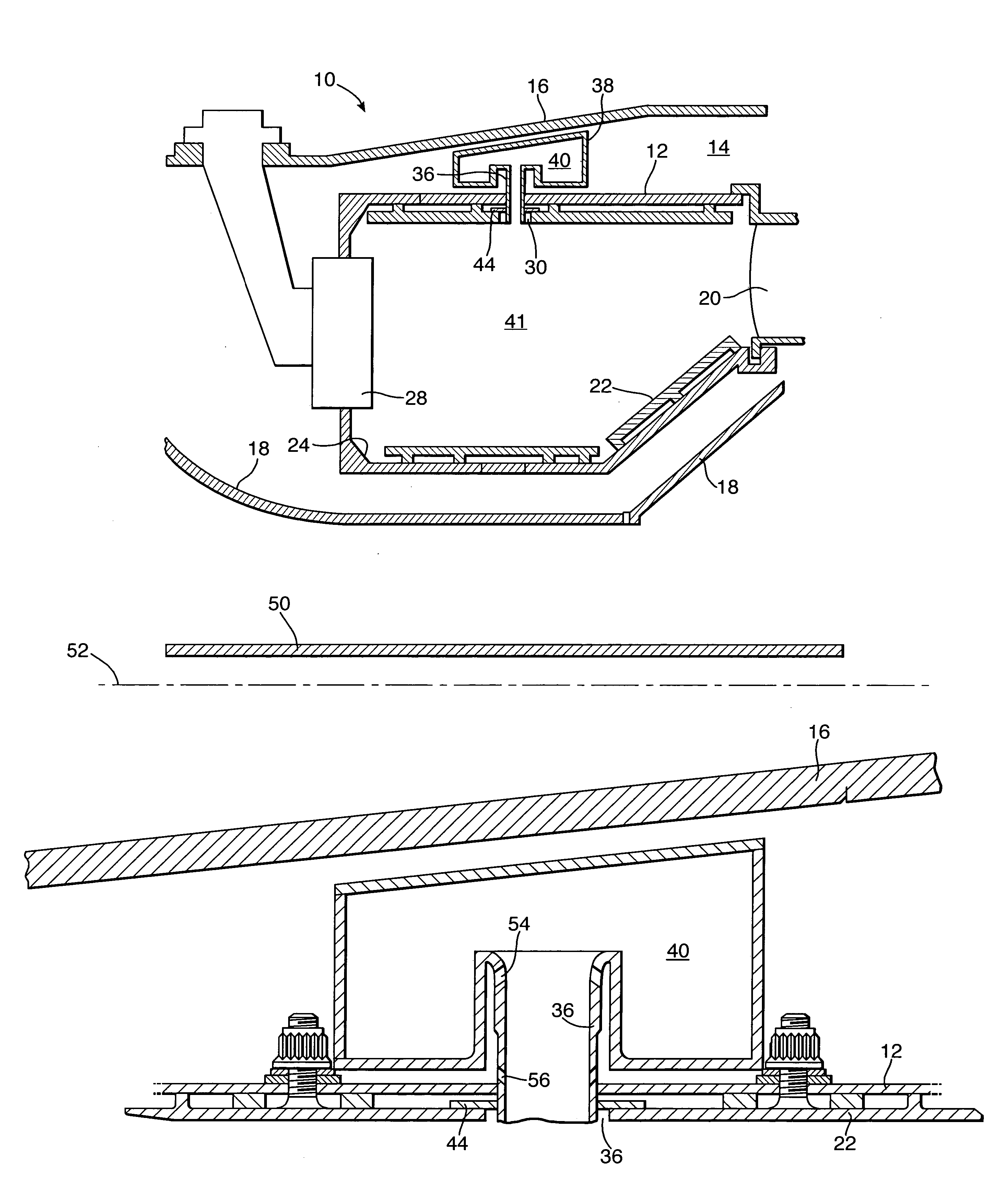
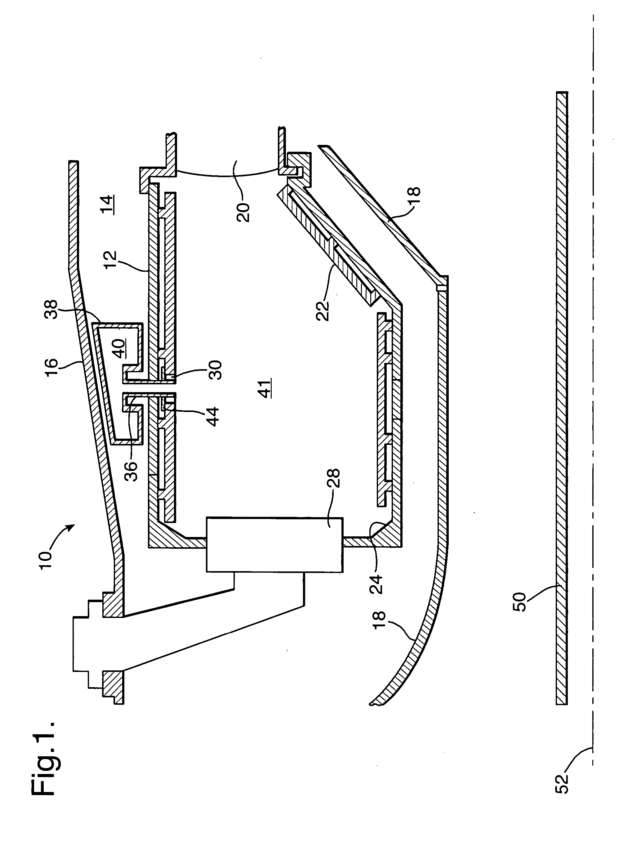
[0021]Referring to FIG. 1, the combustion section 10 of a gas turbine aero engine is illustrated with the adjacent engine parts omitted for clarity, that is the compressor section upstream of the combustor (to the left of the drawing in FIG. 1) and the turbine section downstream of the combustion section. The combustion section comprises an annular type combustion chamber 12 positioned in an annular region 14 between a combustion chamber outer casing 16, which is part of the engine casing structure and radially outwards of the combustion chamber, and a combustion chamber inner casing 18, also part of the engine structure and positioned radially inwards of the combustion chamber 12. The inner casing 16 and outer casing 18 comprise part of the engine casing load bearing structure and the function of these components is well understood by those skilled in the art. The combustion chamber 12 is cantilevered at its downstream end from an annular array of nozzle guide vanes 20, one of whic...


PUM


Abstract

A combustion chamber for a gas turbine engine comprising at least one Helmholtz resonator having a resonator cavity and a resonator neck in flow communication with the interior of the combustion chamber. The cavity extends around at least part of the neck and is spaced apart therefrom to define a cooling chamber therebetween. The cooling chamber allows the neck and the cavity to be cooled with a flow of cooling air. The sunken neck allows the resonator to be located within enclosures with minimal volume without compromising on the damping properties afforded.

Description

CROSS-REFERENCE TO RELATED APPLICATIONS[0001]This application claims priority to Great Britain patent application No. GB 0610800.5, filed 1 Jun. 2006.FIELD OF THE INVENTION[0002]This invention relates to combustion chambers for gas turbine engines, and in particular lean burn, low emission combustion chambers having one or more resonator chambers for damping pressure fluctuations in the combustion chamber in use.BACKGROUND OF THE INVENTION[0003]Lean burn, low emission gas turbine engine combustors of the type now being developed for future engine applications have a tendency, under certain operating conditions, to produce audible pressure fluctuations which can cause premature structural damage to the combustion chamber and other parts of the engine. These pressure fluctuations are audible as rumble which occurs as a result of the combustion process.[0004]Pressure oscillations in gas turbine engine combustors can be damped by using damping devices such as Helmholtz resonators, prefe...

Claims


Application Information

Patent Timeline
Patent Type & Authority Patents(United States)
IPC IPC(8): F01N1/02F02C7/045F01N1/00F23M5/06F02C7/24F23M20/00
CPCF23R3/002F23M20/005F23R2900/00014
Inventor MACQUISTEN, MICHAEL AMORAN, ANTHONY JWHITEMAN, MICHAELCARROTTE, JONATHAN FBARKER, ASHLEY G
Owner ROLLS ROYCE PLC
Why Eureka
Try Eureka