
Image Projecting device

a projecting device and projector technology, applied in the field of image projecting devices, can solve the problems of increasing and/or prolonging the interest of children when animating images or changing between images, and children eventually become disinterested in even the most fascinating images

Inactive Publication Date: 2010-12-28
MATTEL INC
View PDF24 Cites 5 Cited by
  • Summary
  • Abstract
  • Description
  • Claims
  • Application Information

AI Technical Summary

Benefits of technology

[0008]The image projection device also includes a light guide positioned around each light source. The light guide prevents light beams emitted from individual light sources from widening into the path of other light source beams before reaching their respective slide image patterns. In other words, the light guide blocks stray light from entering and allows light to travel through the light guide over which the slide is placed to ensure that individual light beams only reach their corresponding slide image patterns. The resulting image projection system projects multiple images onto a surface while varying the timing and light intensity with which each image is displayed relative to other images.

Problems solved by technology

However, children eventually become disinterested in even the most fascinating images if they are static.
For example, animating an image or changing between images tends to increase and / or prolong a child's interest.

Method used


Image

  • Image Projecting device
  • Image Projecting device
  • Image Projecting device

Examples


Embodiment Construction

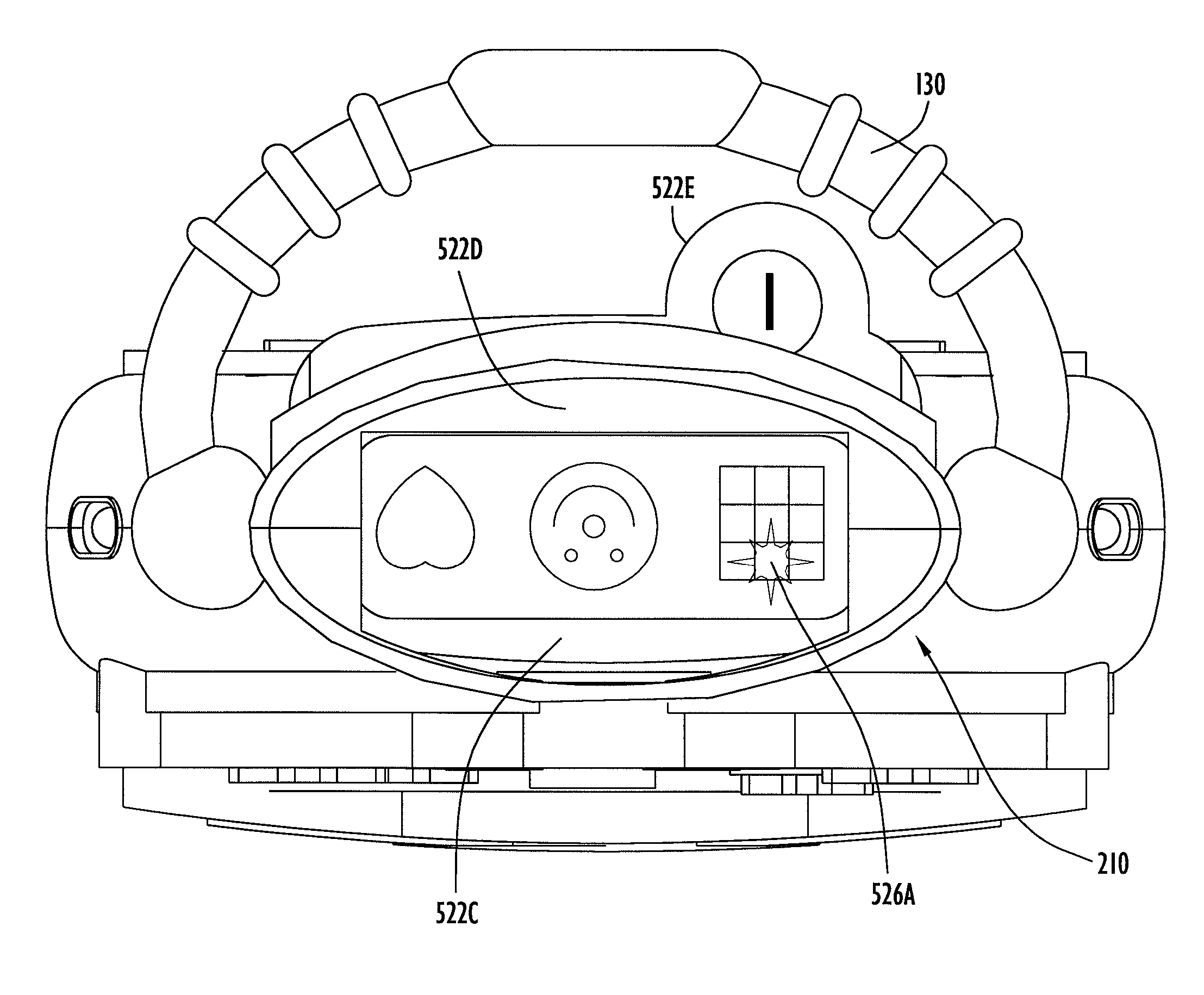
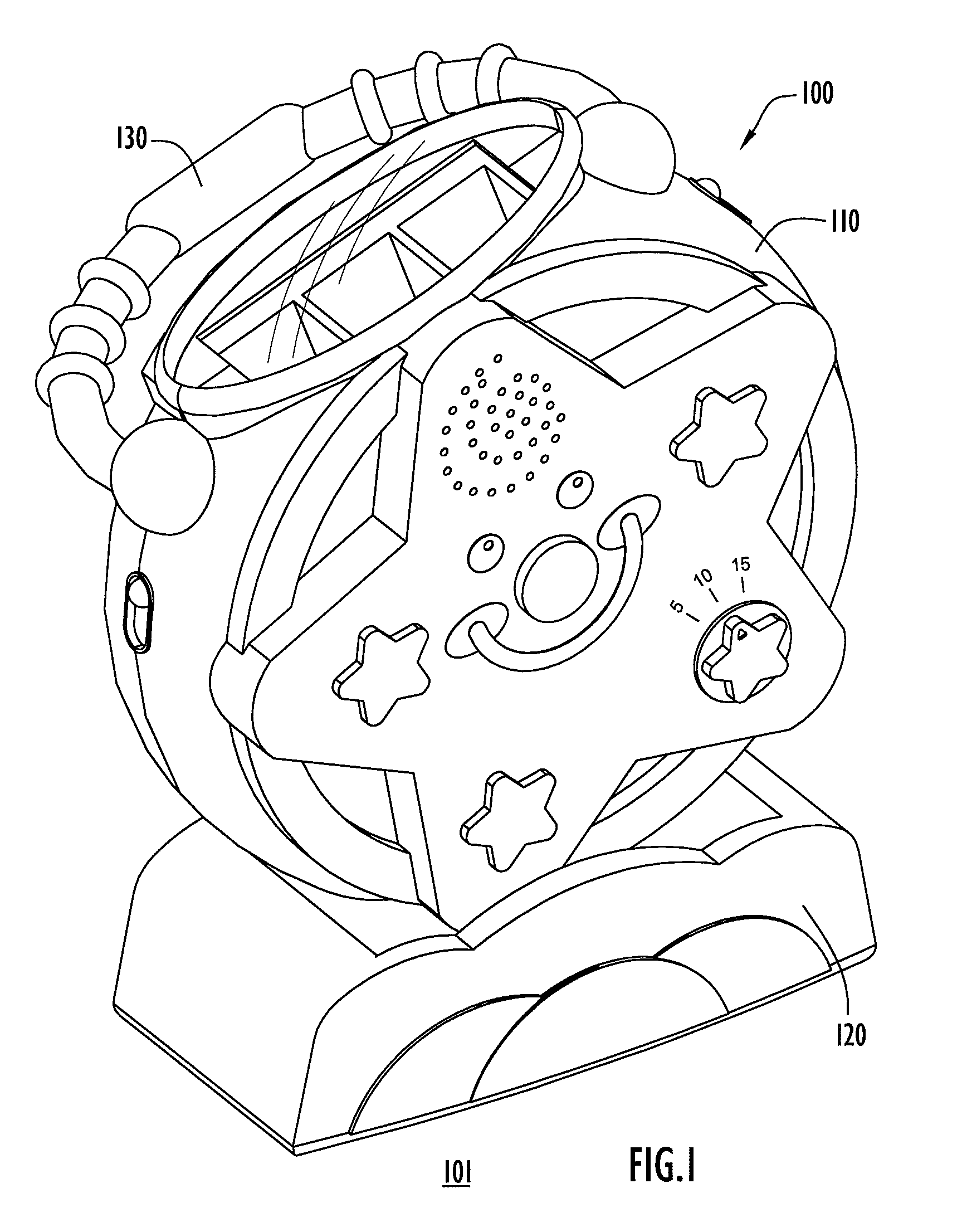
[0032]In accordance with the present invention, an image projection device is disclosed. FIG. 1 illustrates a top perspective view of an embodiment of an image projection device 100. The image projection device 100 includes a housing 110 supported by a base 120 that enables the housing 100 to stand on a supporting surface 101. A handle 130 is pivotally connected to the housing 110 to enable a user to easily transport the image projection device 100.

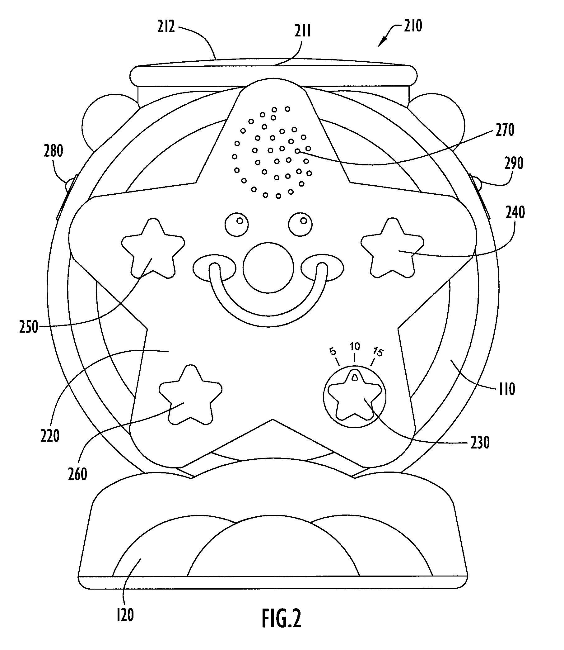
[0033]FIG. 2 illustrates a front view of the image projection device 110 in a first projection orientation or mode. In this embodiment, this mode can be referred to as a ceiling projection mode because the housing 110 is oriented to project light onto a ceiling. The housing 110 includes a light projection portion 210 from which light can emerge to project one or more images. The housing 110 includes an opening 211 formed in its upper end. A plastic cover 212 is disposed in the opening 211. The light projecting from the housing 110 passes ...


PUM


Abstract

An image projection system includes an image projection device for projecting a light image onto a wall, ceiling or other designated surface. The image projection device includes a housing within which is disposed separately located light sources. The housing further includes a slot for receiving several image slides. Each image slide has multiple, separated, slide image patterns thereon and each slide image pattern is in a different location on the image slide. Each of the light sources is disposed in a light chamber such that light from one of the light sources projects through only one of the separated image patterns on the image slide. Light from light sources passing through respective slide image patterns can then intersect to project multiple superimposed images on an image viewing surface. Furthermore, an electronic controller controls the light intensity and light timing of each individual light source.

Description

BACKGROUND OF THE INVENTION[0001]The present invention relates to an image projecting device. Image projectors are commonly used for soothing children. Projectors generally include a housing within which is contained a light generator and in some cases, a sound generator. A parent can generally choose from a combination of attractive images and simultaneous stimulating sounds. Projectors are sometimes contained in a housing that is mounted to a child receiving or supporting device. Other projects can be placed on a flat surface. Some projectors can be reoriented so as to direct a projected image onto different viewing surfaces (e.g., a ceiling, a wall, etc.).[0002]There are many types of images that attract a child's attention. However, children eventually become disinterested in even the most fascinating images if they are static. A more effective way of maintaining a child's interest is to create variety in the image or images. For example, animating an image or changing between i...

Claims


Application Information

Patent Timeline
Patent Type & Authority Patents(United States)
IPC IPC(8): G03B21/14
CPCA63H33/22G03B21/00G09F19/18G03B21/001G03B21/14
Inventor MASTROSIMONE-GESE, MARY G.MAY, GERALD A.WAPLES, DAVID G.
Owner MATTEL INC
Learn More