Combination tool and method for metal-cutting machining of a drill-hole and its hole surface as well as cutting insert for such a combination tool

a combination tool and drill-hole technology, which is applied in the direction of cutting inserts, manufacturing tools, shaping cutters, etc., can solve the problems of deterioration of surface quality, large tolerance differences in the envelope-of-cone-shaped surface of the valve seat, etc., and achieve precise and stable guidance of the cutting insert, high precision, and accurate angular adjustment of the cutting tip

Inactive Publication Date: 2010-12-28
KENNAMETAL INC
View PDF32 Cites 13 Cited by
  • Summary
  • Abstract
  • Description
  • Claims
  • Application Information

AI Technical Summary

Benefits of technology

[0011]Another advantage of the tangential arrangement of the cutting tip, according to one embodiment of the present application, is the fact that the longitudinal or cross extension of the cutting tip, contrary to a radial arrangement, is not oriented radially to the axial centric longitudinal axis and, therefore, usually or essentially requires only very little space in a radial direction. As the space requirement in a radial direction is relatively high in case of a radial orientation, triangular cutting tips are used in particular in case of small diameters of the surfaces to be machined, due to the little space available. With the tangential arrangement described here, a square or polygonal cutting tip may be used, in one example of the present application, in order to keep the tooling costs low.
[0027]In other words, in at least one possible embodiment of the present application, the layers of the cutting insert meet where two small sides abut in a mitered manner, wherein the vertex of the angle of the miter joint is disposed at the corner of the insert base body and the miter joint extends outward from the corner at a 135 degree angle from the small side, to assure or essentially assure that the corners of the cutting insert are uniformly covered with cutting material.

Problems solved by technology

With a conventional radial orientation of the cutting tip, which is usual for combination tools, the large side (base side) of the cutting insert is oriented forwards, viewed in cutting direction, and even slight rotary deviations of the cutting tip from its nominal position will lead to considerable tolerance differences of the envelope-of-cone-shaped surface of the valve seat.
Through such an adjustment, it is achieved that upon a combined infeed, all combination tools simultaneously engage the surface to be machined, as otherwise, irregular and asymmetrical forces would be passed into the common infeed mechanism, which would finally lead to a deterioration of the surface quality.

Method used


Image

  • Combination tool and method for metal-cutting machining of a drill-hole and its hole surface as well as cutting insert for such a combination tool
  • Combination tool and method for metal-cutting machining of a drill-hole and its hole surface as well as cutting insert for such a combination tool
  • Combination tool and method for metal-cutting machining of a drill-hole and its hole surface as well as cutting insert for such a combination tool

Examples


Embodiment Construction

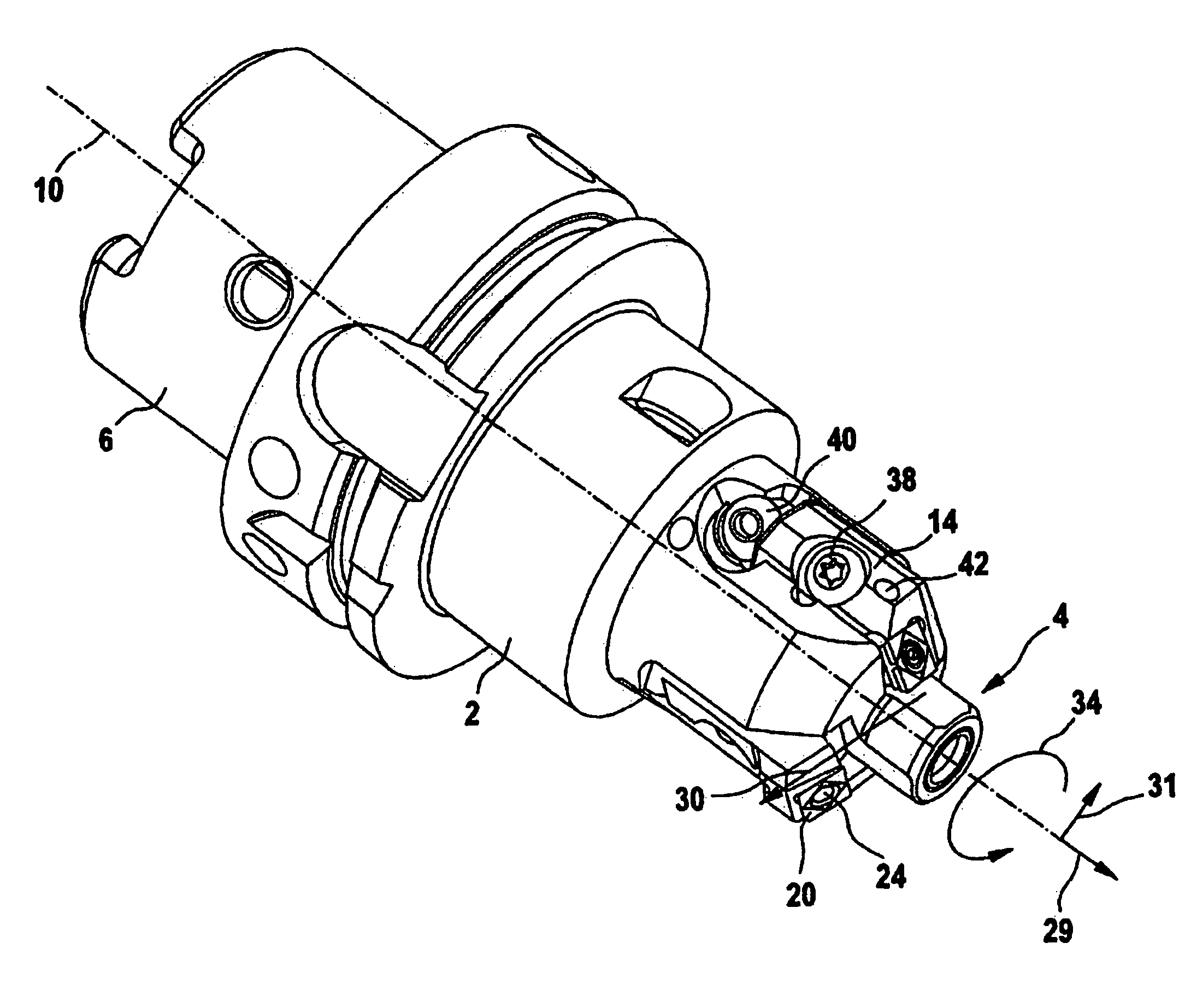
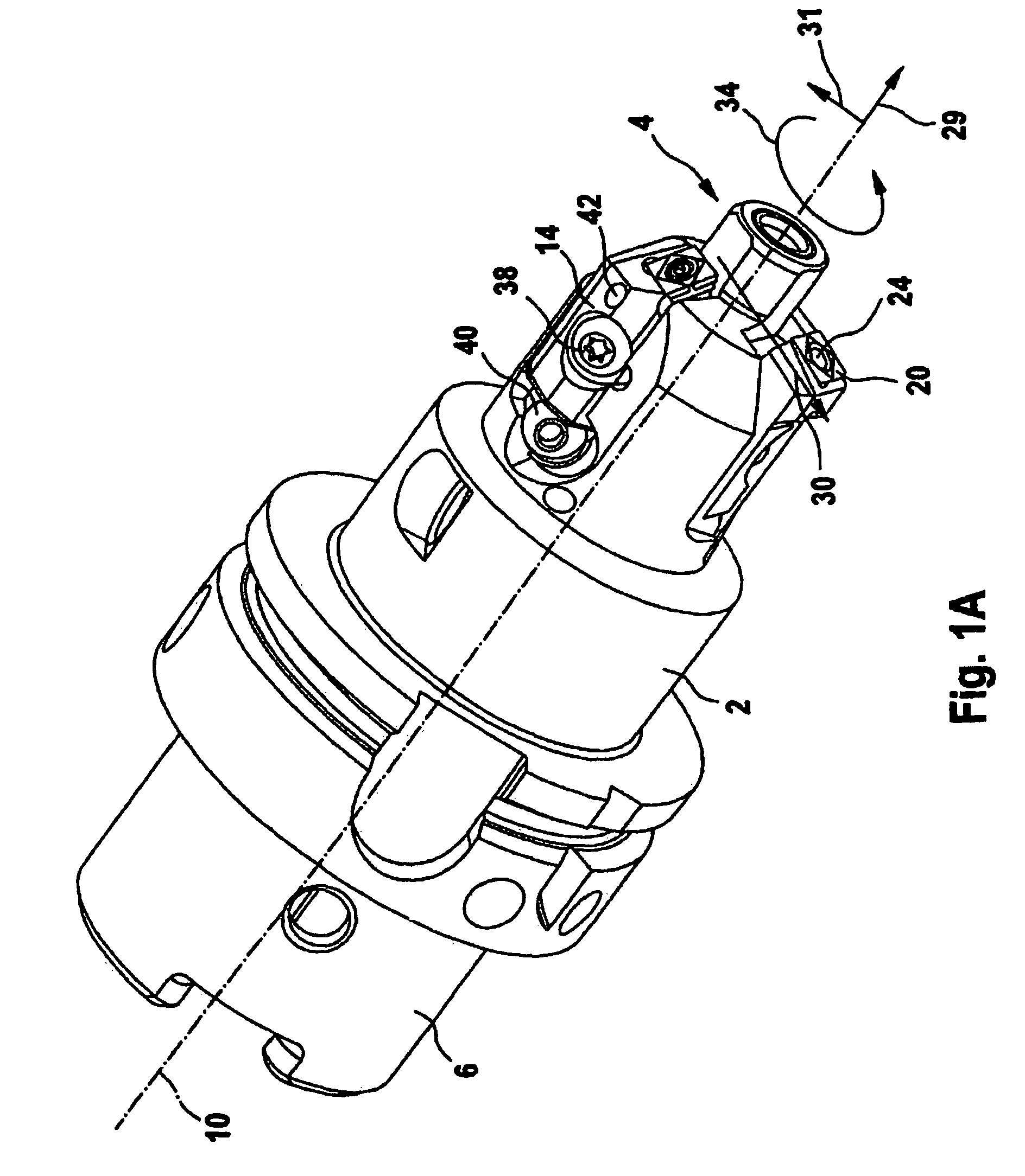
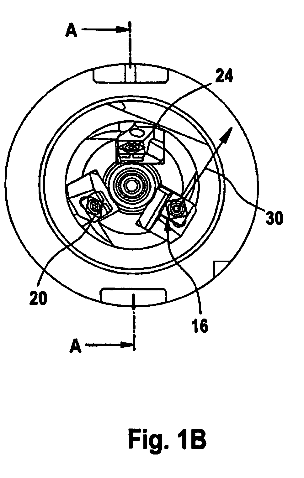
[0053]The combination tool 101 of the exemplary embodiment of FIGS. 1A to 1D comprises a base body 2 of compact and narrow dimensions with an integrated hydraulic expansion chuck 4. The combination tool 101 is connected with a tool spindle by means of a rear connector piece 6. The front end of the expansion chuck 4 includes a cylindrical clamping area 8. The clamping area 8 serves for receiving a turning tool, such as, in at least one possible embodiment, a reamer 78, shown in FIG. 1D. Laterally of the clamping area 8 and spaced radially from a centric longitudinal axis 10 of the combination tool 101, altogether three cassette adaptors or insert holder adaptors, worked into the base body 2 in the manner of grooves or recessed portions, are distributed over the circumference. In the cassette adaptors or insert holder adaptors 12, exchangeable cassettes or insert holders 14, including on their front end face an insert seat 16 with a base bearing face 18, are fastened. One cutting tip ...


PUM

PropertyMeasurementUnit
cone angleaaaaaaaaaa
acute angleaaaaaaaaaa

Abstract

A combination tool and method for metal-cutting machining of a drill-hole and its hole surface as well as cutting insert for such a combination tool.

Description

CONTINUING APPLICATION DATA[0001]This application is a Continuation-In-Part application of International Patent Application No. PCT / EP2007 / 000857, filed on Feb. 1, 2007, which claims priority from Federal Republic of Germany Patent Application No. 10 2006 005 379.6, filed on Feb. 3, 2006. International Patent Application No. PCT / EP2007 / 000857 was pending as of the filing date of this application. The United States was an elected state in International Patent Application No. PCT / EP2007 / 000857.BACKGROUND[0002]1. Technical Field[0003]The present application relates to a combination tool and a method for metal-cutting machining of a drill-hole and its hole surface, such as, in at least one possible embodiment, for metal-cutting machining of a valve stem bushing and its valve seat, the combination tool comprising a base body including a clamping chuck extending in axial direction for a turning tool for machining holes as well as at least one insert seat radially spaced from a centric lon...

Claims


Application Information

Patent Timeline
Patent Type & Authority Patents(United States)
IPC IPC(8): B26D1/00B23B41/00
CPCB23B29/0341B23C3/055B23C5/207B23C5/241B23C5/2427B23C5/2462B23C5/2472B23B31/305Y10T407/23B23B2200/369B23C2200/367B23C2215/60B23C2226/125B23C2226/315B23C2240/08Y10T407/2226Y10T407/27Y10T408/5587Y10T407/1912Y10T407/1932Y10T408/858B23C5/24B23C5/2252B23C5/2226B23C5/202B23B29/034B23B31/30B23C5/20B23C3/05
Inventor LEHMANN, THOMAS CHRISTIANEBERT, GUNTER ALFRED
Owner KENNAMETAL INC
Why Eureka
Try Eureka