
Fluid dispenser for fluid in assay

a technology of fluid dispenser and dispenser, which is applied in the direction of analysis using chemical indicators, laboratory glassware, instruments, etc., can solve the problems of interference with unwanted objects, second is likely, and the inability to combine multi-well plates of a normally used typ

Inactive Publication Date: 2010-12-28
FUJIFILM HLDG CORP +1
View PDF19 Cites 39 Cited by
  • Summary
  • Abstract
  • Description
  • Claims
  • Application Information

AI Technical Summary

Benefits of technology

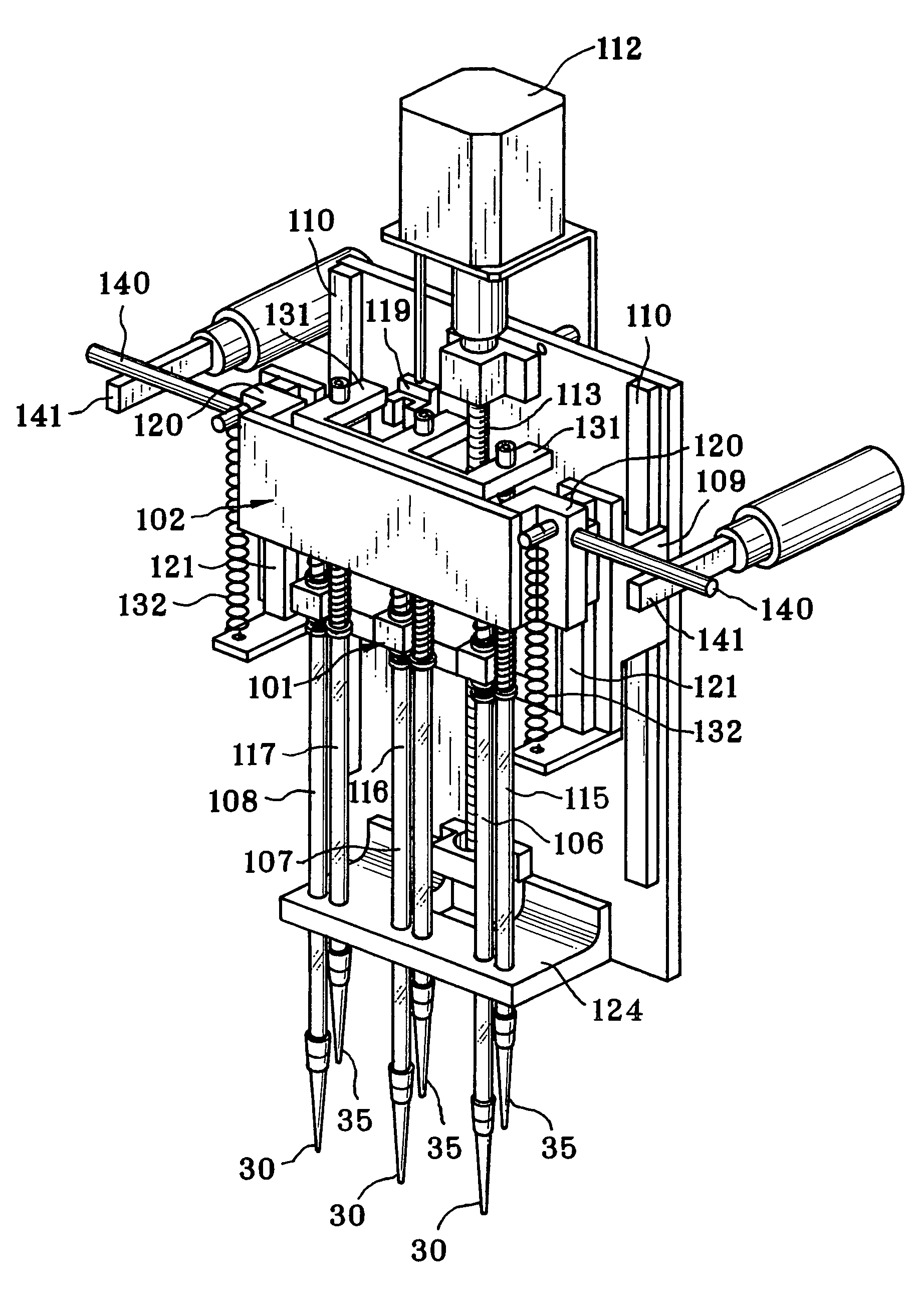
The present invention provides a fluid dispenser with a dispensing head that can move between an aspirating position and an assay position. The dispensing head has two pipette devices, one for aspirating sample and one for dispensing the sample. The dispensing head can be moved up and down using a driving mechanism, and a blocking mechanism prevents the second pipette device from moving down. The fluid dispenser also includes a support mechanism for the pipette devices, a detection projection for detecting the position of the dispensing head, and a stopper for setting the pipette devices in the assay position. The technical effects of the present invention include improved accuracy in fluid dispensing and easier operation of the fluid dispenser.

Problems solved by technology

If both of the pipette devices are moved down, the second is likely to interfere with unwanted objects.
Thus, the multi well plate of a normally used type cannot be used in combination.
If a shifter for moving up and down each pair of the pipette devices is associated with the pipette head, the pipette head has an excessively complicated structure, and has a great size.
Also, a motor must be used for each of the shifters, and will raise the manufacturing cost.
Furthermore, the weight of the pipette head will be very heavy, to lower efficiency in operation due to reduction of the speed of moving the pipette head.

Method used


Image

  • Fluid dispenser for fluid in assay
  • Fluid dispenser for fluid in assay
  • Fluid dispenser for fluid in assay

Examples


Embodiment Construction

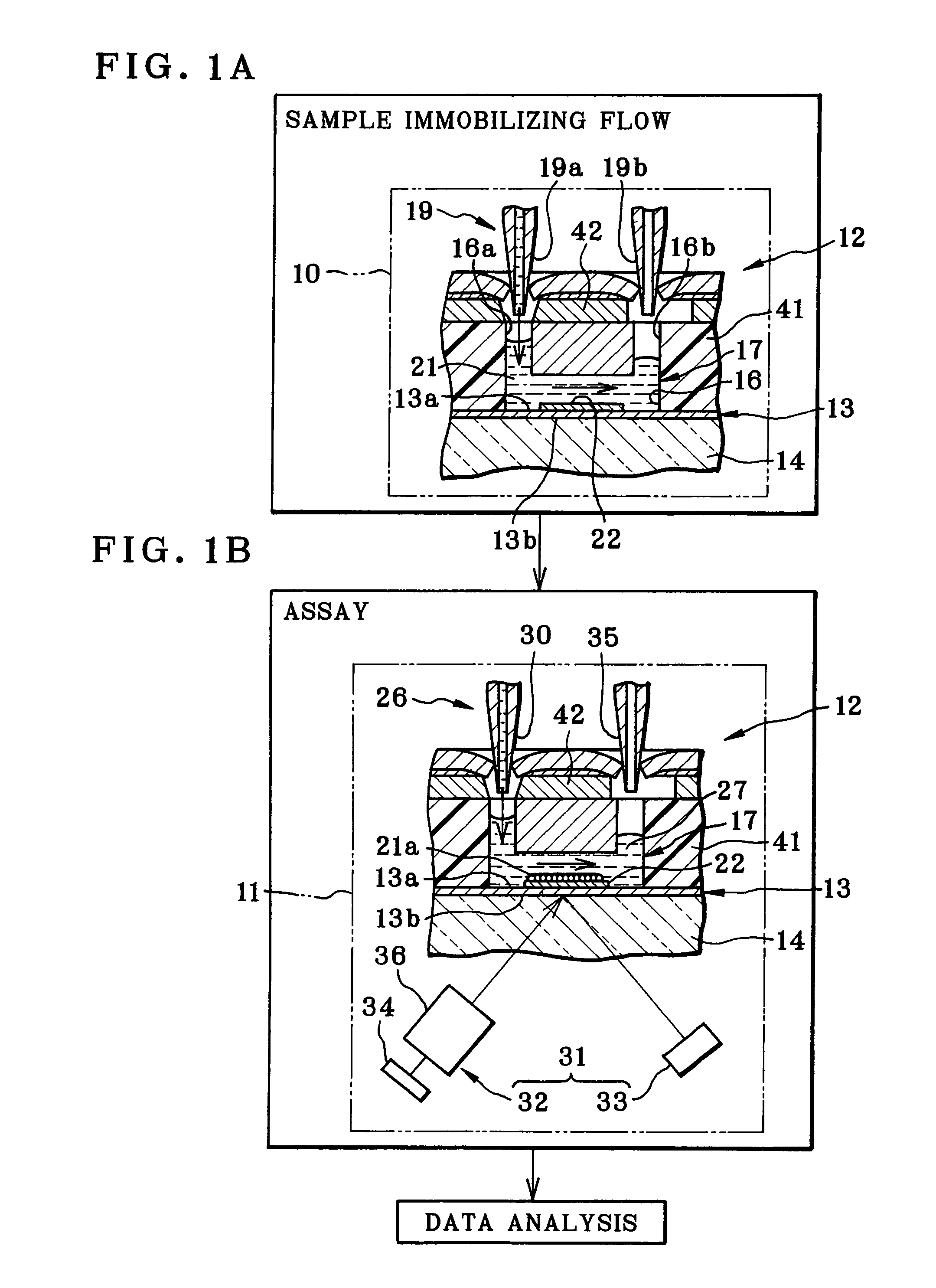
[0047]In FIGS. 1A and 1B, a process of surface plasmon resonance (SPR) assay includes steps of immobilization, assay and data analysis. To this end, an assay system includes sample immobilizing equipment 10, an assay apparatus 11 and a data analyzer 91 of FIG. 4.

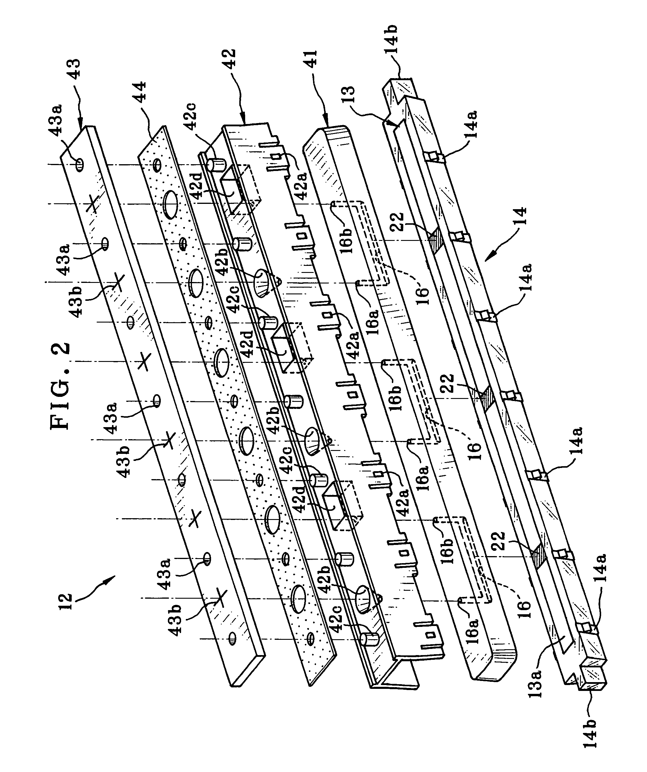
[0048]A sensor unit 12 for SPR assay issued for assay. The sensor unit 12 includes a thin film of metal 13, a prism 14, and a flow channel 16. A sensing surface 13a is a first surface of the thin film 13 to generate surface plasmon resonance. A second surface of the thin film 13 is an interface 13b where the prism 14 is overlaid with the thin film 13, the interface 13b reflecting light by total reflection. The flow channel 16 is opposed to the sensing surface 13a, and is supplied with ligand, analyte or other fluid for flow.

[0049]An example of material for the thin film 13 is gold (Au) or the like. A thickness of the thin film 13 is 50 nm. The thickness can be changed for the suitability in view of the material of the thin f...


PUM


Abstract

A fluid dispenser for surface plasmon resonance (SPR) assay apparatus includes a first pipette device on a first pipette head, and a second pipette device on a second pipette head. In a standby state, the first pipette head is set in an upper position, a coil spring and a stopper set the second pipette head together with the first pipette head, and locate the second pipette head in a high position. While the first and second pipette devices are in an aspirating position, a driving mechanism sets the first pipette head in a lower position. A blocking mechanism sets the second pipette head in a high position against the coil spring. First, third and fifth pipette tips is positioned lower than second, fourth and sixth pipette tips, to access a well. The first to sixth pipette tips, while in an assay position, are equally lowered.

Description

BACKGROUND OF THE INVENTION[0001]1. Field of the Invention[0002]The present invention relates to a fluid dispenser for fluid in assay. More particularly, the present invention relates to a fluid dispenser for fluid in assay, in which pipette devices can be moved up and down selectively even with a simple structure of a pipette head.[0003]2. Description Related to the Prior Art[0004]An assay apparatus for assay in utilizing attenuated total reflection is used for various kinds of studies in a biochemical field or the like, for example to study interaction of protein, DNA and various biomaterials, and to select candidate drugs by screening. Also, the technique is useful in the fields of the clinical medicine, food industries and the like.[0005]A surface plasmon resonance (SPR) sensor is known as an assay apparatus for assay in utilizing attenuated total reflection. A thin film / dielectric interface of a metal film is fitted on a dielectric block. Light is directed to the thin film / diel...

Claims


Application Information

Patent Timeline
Patent Type & Authority Patents(United States)
IPC IPC(8): B01L3/02
CPCB01L3/021G01N35/1095B01L2200/022B01L2300/0829G01N21/553
Inventor MURAISHI, KATSUAKIFUJIKURA, TATSUOTAKAI, SHINYA
Owner FUJIFILM HLDG CORP
Learn More