

Electrolytic capacitor and method of producing the same
a technology of electrolyte capacitor and capacitor, which is applied in the direction of liquid electrolytic capacitor, casing/cabinet/drawer details, electrical apparatus casing/cabinet/drawer, etc., can solve the problem that none of the electrolyte capacitors set forth above has sufficient withstand voltage, etc., to achieve low leakage current, low esr, and high withstand voltage
- Summary
- Abstract
- Description
- Claims
- Application Information
AI Technical Summary
Benefits of technology
Problems solved by technology
Method used
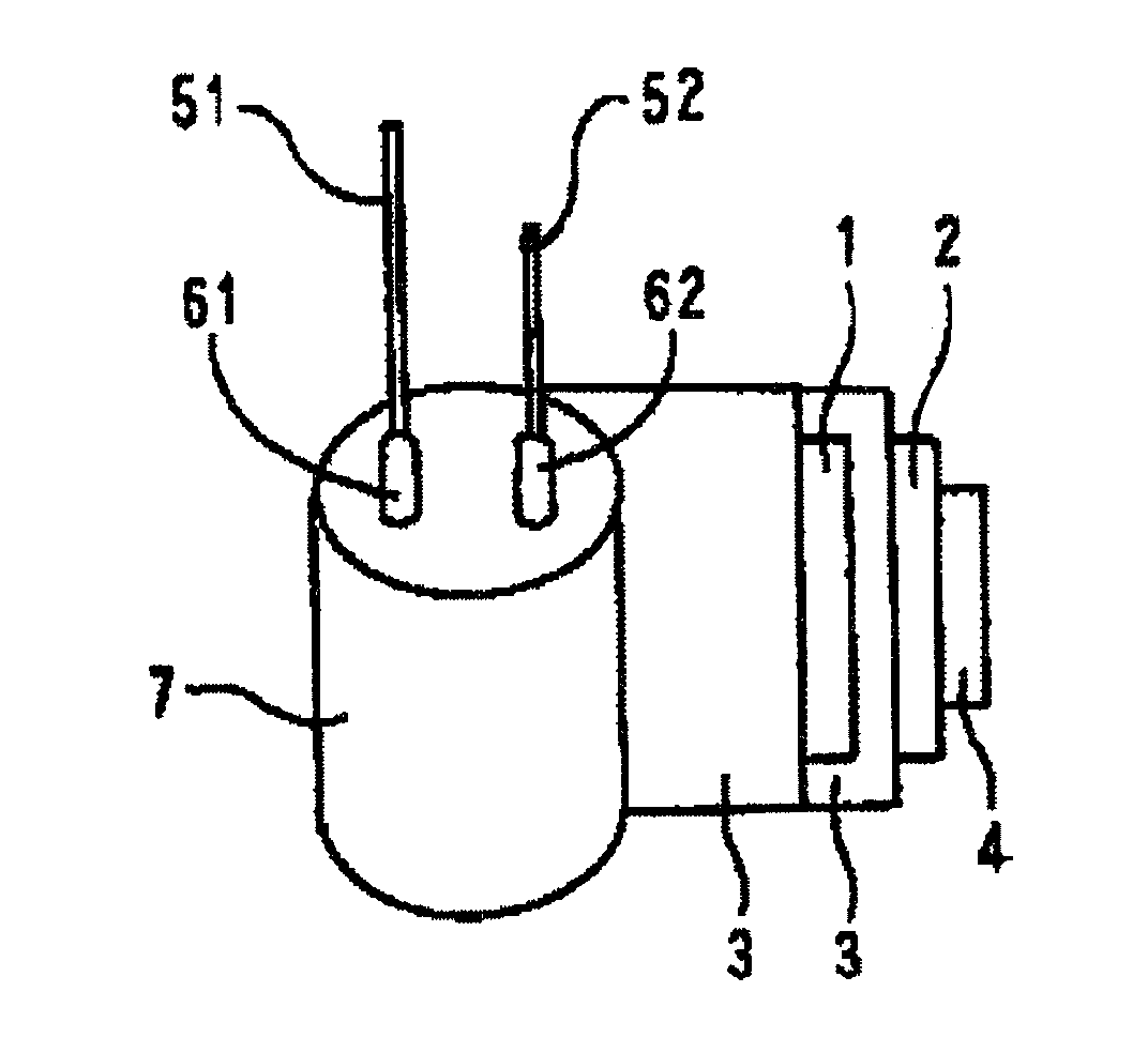
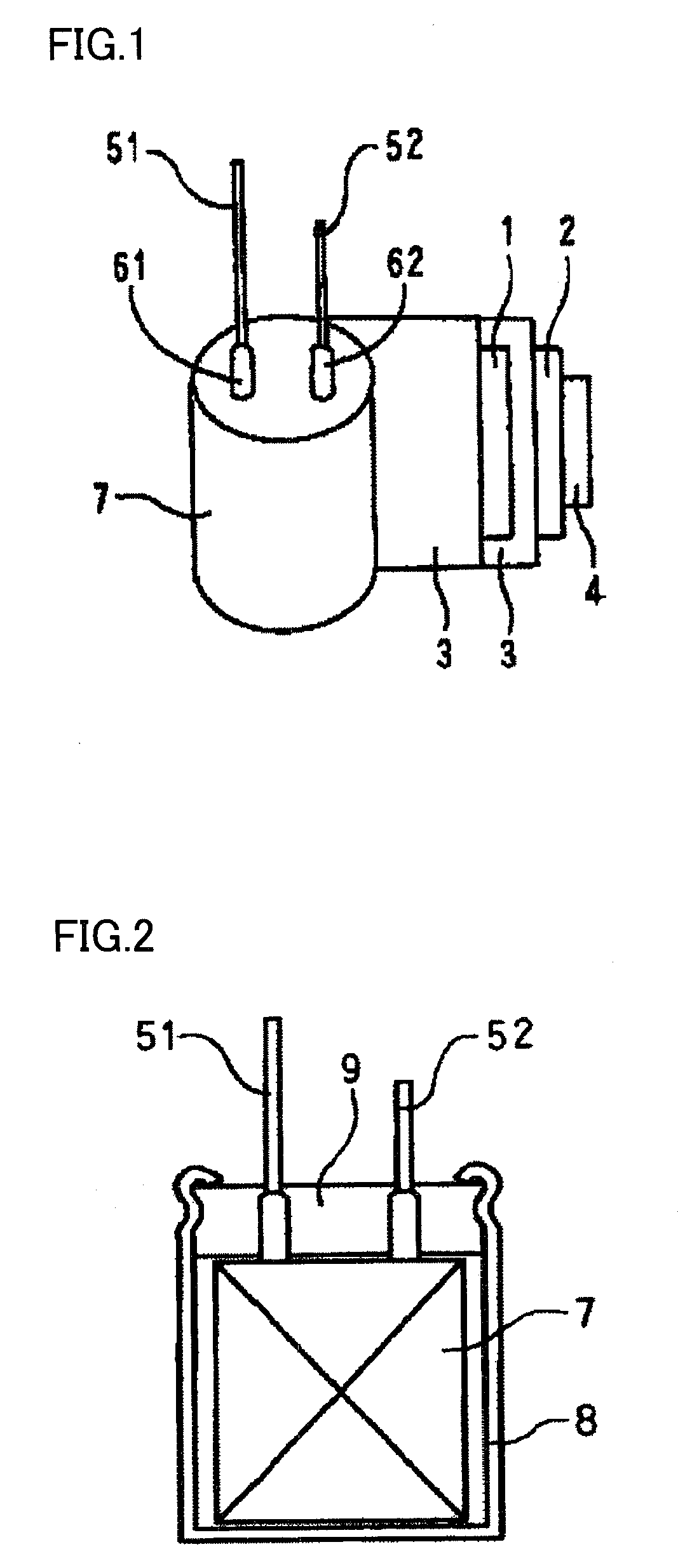
Image

Examples
example 1
(1) Preparation of Conductive Solid Containing Dispersion
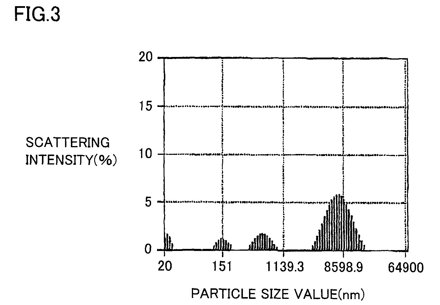
[0069]A solution having 3,4-ethylenedioxythiophene and polystyrene sulfonic acid serving as a dopant (molecular weight; approximately 150000) dissolved in ion exchange water was mixed at 20° C. While agitating the mixed obtained solution kept at 20° C., an oxidization catalyst solution of ammonium persulfate and ferric sulfate dissolved in ion exchange water was added. Agitation was carried out for 3 hours to cause reaction. The obtained reaction solution was dialyzed to remove unreacted monomer and the oxidation catalyst. A solution including approximately 1.5 mass % of blue polystyrenesulfonic acid doped poly(3,4-ethylenedioxylthiophene) was obtained. Then, imidazole was dispersed uniformly in this solution to obtain a conductive solid containing dispersion. The results of the particle size distribution measurement through a dynamic laser light scattering method in accordance with the measurement method set forth above of th...
examples 2 and 3
[0073]Electrolytic capacitors were produced in a manner similar to the method of Example 1, provided that the rated voltage, nominal capacitance, finished dimension (mm in diameter×mm in height), and forming voltage of the employed wound-type capacitor element were those shown in Table 1. The capacitance, ESR, tan δ (tangent of loss angle), and leakage current (LC) were measured for these electrolytic capacitors. The results are shown in Table 1.
PUM
| Property | Measurement | Unit |
|---|---|---|
| particle size distribution | aaaaa | aaaaa |
| particle size | aaaaa | aaaaa |
| pore diameter | aaaaa | aaaaa |
Abstract
Description
Claims
Application Information