Device and method for positioning a target volume in radiation therapy apparatus

a radiation therapy and target volume technology, applied in the field of radiation therapy, can solve the problems of beam damage to healthy cells within the patient's body, and achieve the effect of good intersection point precision

Inactive Publication Date: 2010-12-28
ION BEAM APPL
View PDF8 Cites 152 Cited by
  • Summary
  • Abstract
  • Description
  • Claims
  • Application Information

AI Technical Summary

Benefits of technology

[0027]Preferably, the radiation detector and radiation beam are arranged such that said radiation beam intersects said detector in a substantially perpendicular direction, thereby providing a good precision in the intersection point.

Problems solved by technology

Otherwise, the beam could damage healthy cells within the patient's body.

Method used


Image

  • Device and method for positioning a target volume in radiation therapy apparatus
  • Device and method for positioning a target volume in radiation therapy apparatus
  • Device and method for positioning a target volume in radiation therapy apparatus

Examples


first embodiment

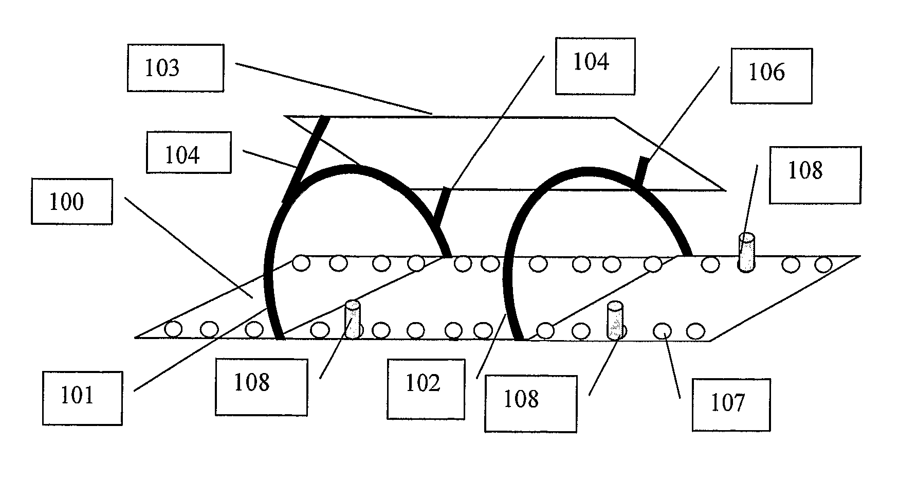
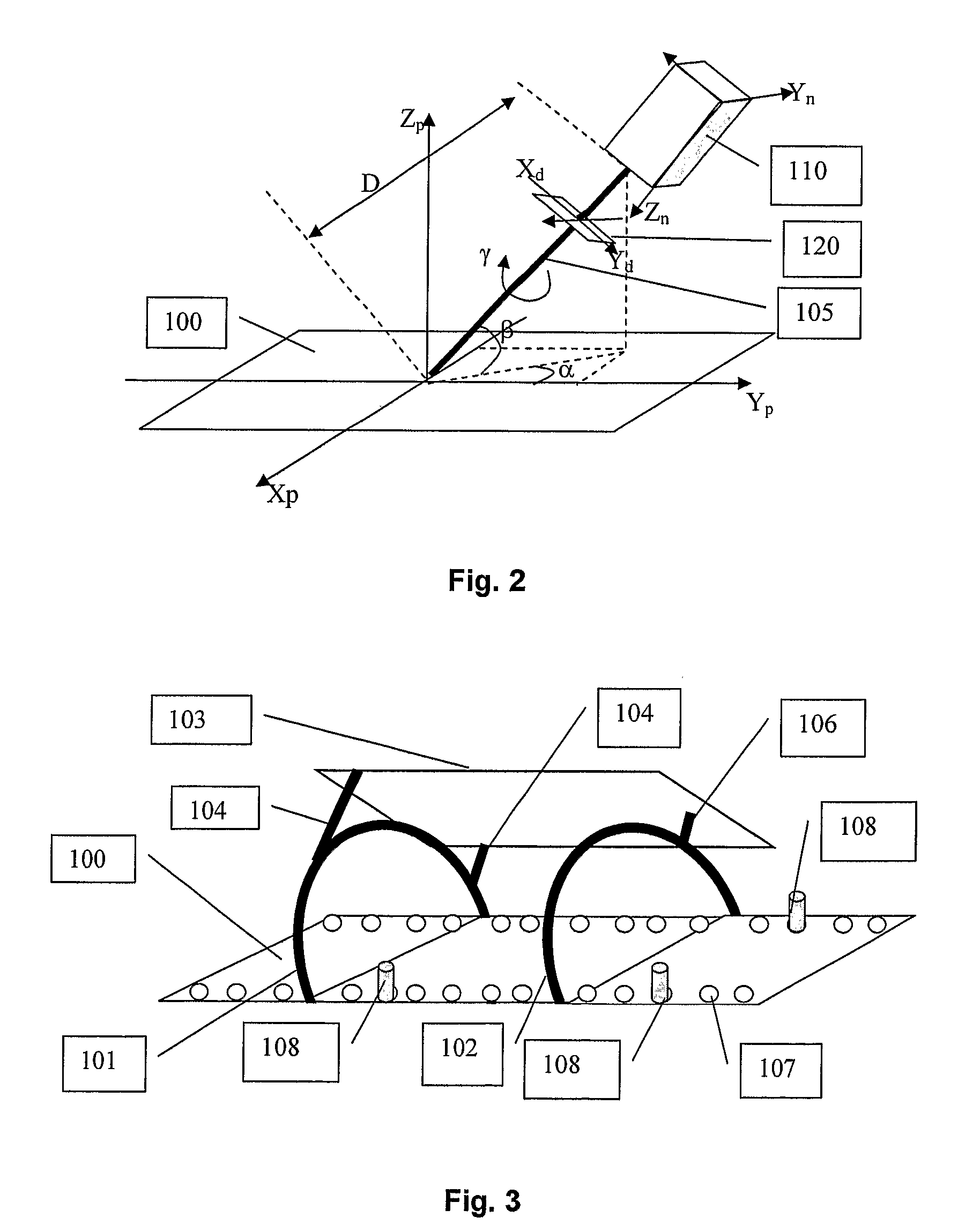
[0068]Two frames are attached to the couch. Several types of frames assembly are possible: in a first embodiment, the frames are shaped as half circles (FIG. 3). The two frames 101 and 102 are fixed to the couch 100 using the fixation holes 107. The fixation holes 107 used to attach the frames 101 and 102 are selected so that the distance between the approximate position of tumour in the patient and the first frame 101 is substantially equal to the distance between the tumour and the second fixation frame 102. Therefore, the tumour is approximately in the middle between the two fixation frames. The half circle frames can be attached to the top of the couch if the particle beam is coming from above the couch. Alternatively, they can be fixed to the bottom of the couch if the particle beam comes from under the couch. FIG. 3 represents only the configuration when the proton beam is coming from above the couch. There are fixation holes 401 equidistantly drilled on the rim of the circula...

third embodiment

[0070]In a third embodiment, the frames have a non circular shape, for example they can have a trapezoidal shape (FIG. 5). The two trapezoidal frames 301 and 302 are fixed to the couch 100 using the fixation holes 107. There are two fixation holes on each side of the trapezoidal fixation frame 301. There is one fixation hole on each side of the trapezoidal frame 302. The legs 304, 305 and 306 of the radiation detector 103 are inserted in the fixation holes. In this embodiment, the radiation detector can be at three different positions around the patient.

[0071]The method of patient positioning comprises two steps: a first step of calibration of the radiation detector prior to the treatment, and a second step of actually positioning the patient during treatment

[0072]The first step, calibration of the radiation detector, is described hereafter: When a new radiation detector is used, it must be calibrated. Indeed, the radiation detector measures the distribution of the radiation intensi...


PUM

PropertyMeasurementUnit
displacementaaaaaaaaaa
volumeaaaaaaaaaa
computed tomographyaaaaaaaaaa

Abstract

Device for positioning a target volume (112) such, as a phantom or a patient in a radiation therapy apparatus, said apparatus directing a radiation beam (405) towards said target (112), characterized in that it comprises:—a target support (100) whereon the target is immobilized; a two dimensional radiation detector (103) fixed with fixations means (101, 102, 104, 106 107; 301, 302, 304, 305, 306; 208, 209) in a known geometric relationship to said target support (100), said radiation detector (103) being capable of detecting the position of intersection of said radiation beam (105) with said detector (103); correcting means for correcting the relative position of said beam (105) and said target support 100), based on said detected intersection position.

Description

TECHNICAL FIELD[0001]The invention relates to the field radiation therapy. More particularly, the invention relates to a device and method for positioning a target volume in a radiation therapy apparatus. Said target can be a patient or a phantom representing said patient for irradiation tests.DESCRIPTION OF RELATED ART[0002]When a tumour has been discovered in a patient's body, the tumour first needs to be visualized for further diagnostic. This can for example be performed with an imaging system such as a computed tomography (CT) scanning system or an MRI apparatus. A 3D representation of the tumour volume is obtained. With the information collected in this way a clinical treatment plan can be generated. Then the actual treatment with a radiation therapy apparatus can start.[0003]In a known hadron therapy apparatus, like e.g. used in proton therapy, the therapeutic radiation beam, accelerated by an accelerator such as a cyclotron, is guided to the therapy room, where the patient i...

Claims


Application Information

Patent Timeline
Patent Type & Authority Patents(United States)
IPC IPC(8): G01K5/08
CPCA61N5/1049A61B6/0421A61N5/1065A61N5/1069A61N2005/1087A61N5/10
Inventor JONGEN, YVESLABARBE, RUDI
Owner ION BEAM APPL
Why Eureka
Try Eureka