Vehicle occupant classification system
a classification system and vehicle technology, applied in vehicular safety arrangments, electric devices, process and machine control, etc., can solve the problems of inability to distinguish between passengers and and the inability of current occupant detection systems to deploy airbags and corresponding occupant detection systems to provide reliable means
- Summary
- Abstract
- Description
- Claims
- Application Information
AI Technical Summary
Benefits of technology
Problems solved by technology
Method used
Image
Examples
second embodiment
[0084]Referring now to FIGS. 12 and 13, a seat cushion portion 14′ and a pressure sensor 18′ in accordance with a second embodiment will now be explained. In view of the similarity between the first and second embodiments, the parts of the second embodiment that are identical to the parts of the first embodiment will be given the same reference numerals as the parts of the first embodiment. Moreover, the descriptions of the parts of the second embodiment that are identical to the parts of the first embodiment may be omitted for the sake of brevity. The parts of the second embodiment that differ from the parts of the first embodiment will be indicated with a single prime (′)
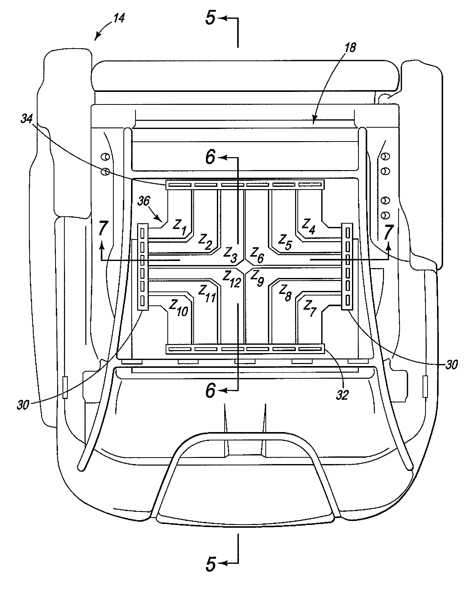
[0085]The pressure sensor 18 of the first embodiment has a plurality of zones Z1-Z12. The level of sensitivity of the pressure sensor 18 far exceeds the needs of current airbag deployment systems. Specifically, the pressure sensor 18 can easily measure the weight of a passenger seated in the seat cushion portion 1...
third embodiment
[0089]Referring now to FIG. 14, a pressure sensor 18″ within a seat cushion portion in accordance with a third embodiment will now be explained. In view of the similarity between the first and third embodiments, the parts of the third embodiment that are identical to the parts of the first embodiments will be given the same reference numerals as the parts of the first embodiment. Moreover, the descriptions of the parts of the third embodiment that are identical to the parts of the first embodiment may be omitted for the sake of brevity. The parts of the third embodiment that differ from the parts of the first embodiment will be indicated with a double prime (″).
[0090]The pressure sensor 18″ is a single pressure sensor disposed within the depicted seat cushion portion and can be a single zone pressure sensor, like the pressure sensor 18′ of the second embodiment, or can have any number of zones, similar to the zones Z1-Z12 of the pressure sensor 18 of the first embodiment. The pressu...
fourth embodiment
[0091]Referring now to FIG. 15, pressure sensors 18a and 18b within a seat cushion portion in accordance with a fourth embodiment will now be explained. In view of the similarity between the first and fourth embodiments, the parts of the fourth embodiment that are identical to the parts of the first embodiments will be given the same reference numerals as the parts of the first embodiment. Moreover, the descriptions of the parts of the fourth embodiment that are identical to the parts of the first embodiment may be omitted for the sake of brevity.
[0092]The seat cushion depicted in FIG. 15 is contoured such that two pressure sensors such as the pressure sensors 18a and 18b are more suitable for approximating the weight of a passenger. The pressure sensor 18a can be a single zone pressure sensor, like the pressure sensor 18′ of the second embodiment, or can have any number of zones, similar to the zones Z1-Z12 of the pressure sensor 18 of the first embodiment. Similarly, the pressure ...
PUM
 Abstract
Description
Claims
Application Information
 - R&D
- Intellectual Property
- Life Sciences
- Materials
- Tech Scout
- Unparalleled Data Quality
- Higher Quality Content
- 60% Fewer Hallucinations
Browse by: Latest US Patents, China's latest patents, Technical Efficacy Thesaurus, Application Domain, Technology Topic, Popular Technical Reports.
© 2025 PatSnap. All rights reserved.Legal|Privacy policy|Modern Slavery Act Transparency Statement|Sitemap|About US| Contact US: help@patsnap.com


