
Eco-run control device and method for resetting the same

a control device and eco-run technology, applied in the direction of electric control, engine starters, instruments, etc., can solve the problems of eco-run ecu frequently reset, communication might become invalid, and the driver feels uneasy

Inactive Publication Date: 2010-12-28
FUJITSU GENERAL LTD
View PDF26 Cites 39 Cited by
  • Summary
  • Abstract
  • Description
  • Claims
  • Application Information

AI Technical Summary

Benefits of technology

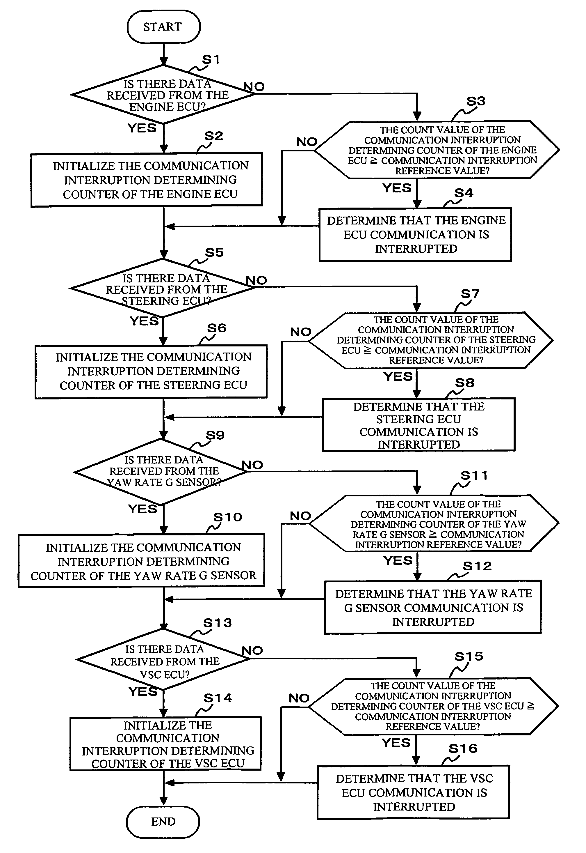
The present invention provides an eco-run control device and a method for resetting the device that overcomes the disadvantages of previous versions. Specifically, the invention restricts eco-run control against the user's will by monitoring the state of the ignition and communicating with other control devices that receive power from a power supply line that is connected to a power source via the ignition. The device can also put the engine into a started state when receiving an eco-run prohibiting request, even if the ignition is in an OFF state and communications with other control devices are interrupted. The invention also includes an initialization controlling unit that initializes data with respect to the eco-run control stored in a memory when the monitoring unit determines that the ignition is in an OFF state and the communications with two or more of the control devices are interrupted. The technical effects of the invention include improved eco-run control and better user experience.

Problems solved by technology

This makes the driver feel uneasy.
Therefore, when the IG line is temporarily disconnected at the time of a low voltage, communications might become invalid.
Accordingly, there is a possibility that the eco-run ECU is frequently reset when the voltage is low.
Japanese Unexamined Patent Publication No. 2004-17676 does not disclose a method for determining whether the ignition switch is switched off by an operation of the ignition key or temporary disconnection of the IG line.

Method used


Image

  • Eco-run control device and method for resetting the same
  • Eco-run control device and method for resetting the same
  • Eco-run control device and method for resetting the same

Examples


embodiment

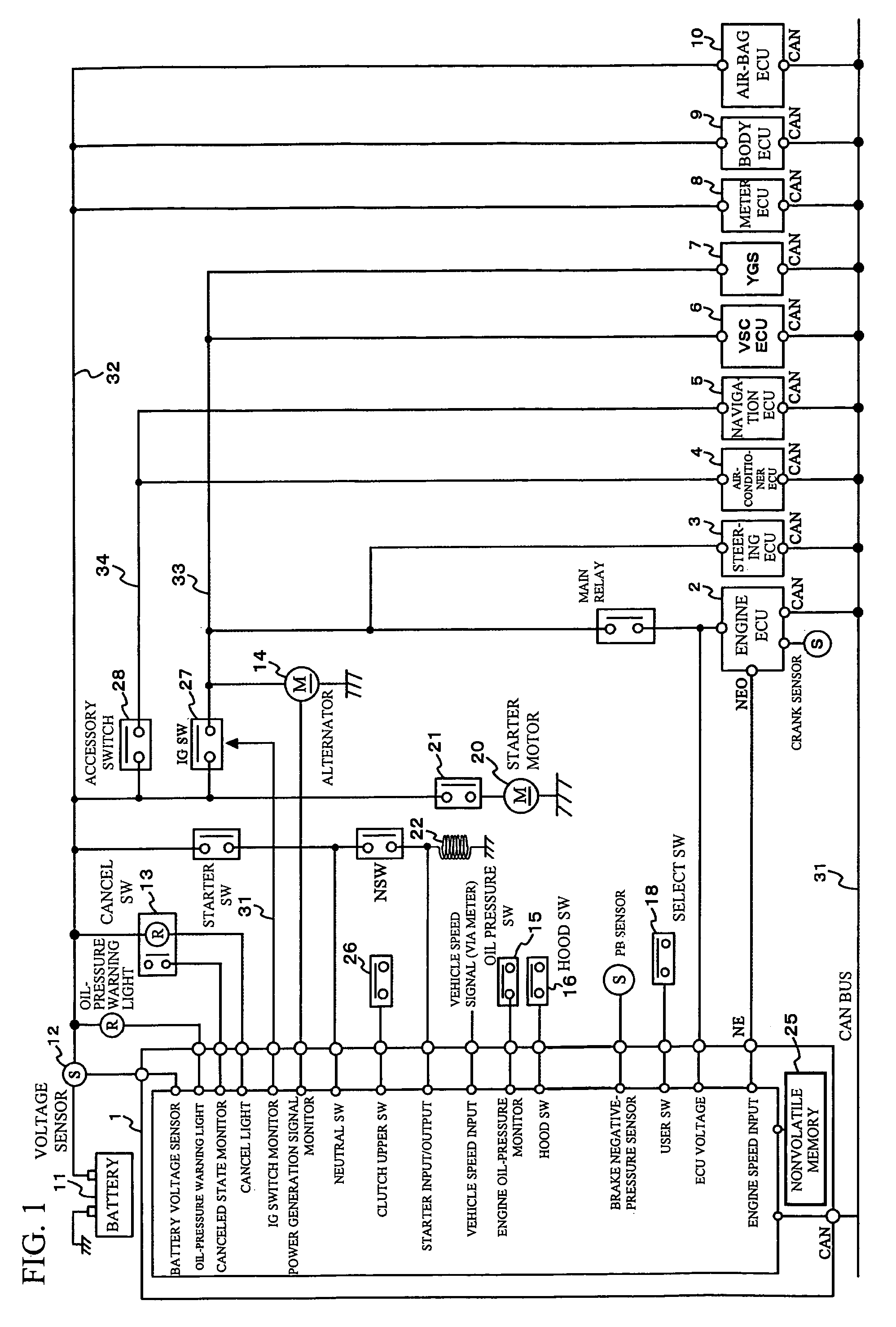
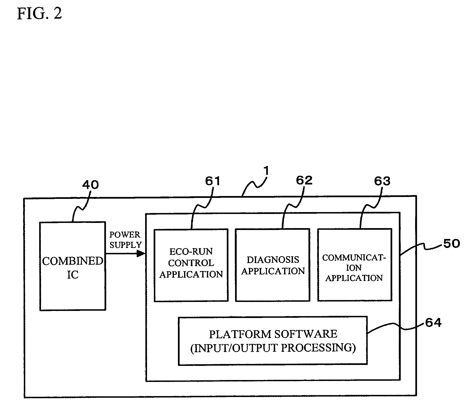
[0027]Referring first to FIG. 1, the structure of this embodiment is described in detail. In this embodiment, an eco-run ECU (this eco-run ECU includes the initialization controller, the engine start controller, the engine start control prohibiting unit, and the engine state controller of the present invention) 1 and nodes are connected to a CAN (Controller Area Network) bus 31. In FIG. 1, an engine ECU 2, a steering ECU 3, an air conditioner ECU 4, a navigation ECU 5, a vehicle stability control ECU (hereinafter referred to as VSC ECU) 6, a yaw rate G sensor 7, a meter ECU 8, a body ECU 9, and an air bag ECU 10 are shown as the nodes that perform CAN communications with the eco-run ECU 1. However, the nodes are not limited to those nodes.

[0028]Each of the nodes receives a power supply from a battery 11 to operate. The eco-run ECU 1, the meter ECU 8, the body ECU 9, and the air bag ECU 10 are connected to a +B line 32 that is connected directly to the +-pole of the battery 11. The e...


PUM


Abstract

An eco-run control device is mounted on a vehicle and is capable of performing eco-run control to stop an engine when predetermined stop requirements are satisfied and restart the engine when predetermined start requirements are satisfied later. This eco-run control device includes: a monitoring unit that monitors the state of an ignition; a communicating unit that communicates with a plurality of control devices that receive power supplies from a power supply line that is connected to a power source via the ignition; and an initialization controlling unit that initializes the data with respect to the eco-run control stored in a memory, when the monitoring unit determines that the ignition is in an OFF state, and that the communications with two or more of the control devices are interrupted.

Description

BACKGROUND OF THE INVENTION[0001]1. Field of the Invention[0002]The present invention relates to an eco-run control device that has an eco-run function to drive a vehicle while starting and stopping the engine.[0003]2. Description of the Related Art[0004]In recent years, to improve fuel efficiency and reduce emission, eco-run control devices are mounted on vehicles. An eco-run control device issues an engine stop instruction when predetermined engine stop requirements are satisfied, and later issues an engine restart instruction to drive an engine starting motor when predetermined engine start requirements are satisfied.[0005]An eco-run ECU that performs eco-run control operations determines whether to stop the engine and whether to start the engine, based on an eco-run allowing signal and an eco-run prohibiting signal transmitted from another ECU, and signals transmitted from various sensors and actuators.[0006]An eco-run ECU and most ECUs cooperating with the eco-run ECU form a so...

Claims


Application Information

Patent Timeline
Patent Type & Authority Patents(United States)
IPC IPC(8): F02N11/08F02D17/00F02D15/00F02D29/02
CPCF02D41/266F02N11/0818F02D41/042F02D41/2493F02N11/10F02N2250/02F02N2300/30F02N2300/304F02P11/025Y02T10/48Y02T10/40
Inventor YAMAGUCHI, KAZUHI
Owner FUJITSU GENERAL LTD
Learn More