Non-
ambulatory patients who must be supported and moved in a patient facility such as a hospital or a
nursing home present substantial challenges when a course of treatment for such patients calls for movement from one location to another.
In the case of a patient being returned to a hospital room following
surgery, for example, the patient's body may not be able to withstand the stresses and strains of being lifted from a stretcher to the
bed when one or even several hospital personnel combine their efforts to make such a transfer.
The same challenge of moving a patient with minimum handling exists in non-surgical settings as well.
When such a patient is categorized as morbidly obese, transfers present difficulties for both the patient and the
care facility staff.
The staff must perform the task of lifting and / or sliding such a patient because in nearly all instances the patient, due to the physical condition of
obesity and / or illness, simply cannot do the task alone.
The manipulation of such a person requires a plurality of hospital staff since such manipulation is impossible to perform by a single person such as a floor nurse assigned to the patient's room.
Gathering together such a large number of people four times at often uncertain intervals to provide but a
single cycle of treatment to a patient raises obvious logistical problems and, in addition, erodes the quality of care the facility can render by reason of the application of such a large number of personnel to deal with but a
single patient treatment episode.
A further drawback to such a patient
handling system as above described is that, even with the best intentioned and caring of staff, the patient very often suffers substantial discomfort.
The simple act of sliding a patient over a flat surface can be very painful to a patient who has had surgical incisions which are far from healed, for example.
A problem common to all such devices however is that invariably the
air mattress has the general characteristic of a
balloon in the sense that when one area is indented another
remote area will bulge, thus creating an unstable condition.
If for example a stretcher carrying an obese person makes a sharp turn during a trip to or from a treatment location, such an obese person will tend to roll toward the outside of the turn due to the
instability of such a conventional
air mattress.
In effect, the conventional mattress reinforces the undesirable rolling movement and hence can be termed to be unstable.
Since much of the time the patient is incapable of stopping the rolling action alone the patient may
roll off the stretcher onto the floor with disastrous consequences.
Indeed, even in the instance of a patient who is capable of moving themselves to some degree about their longitudinal
body axis the same disastrous result may occur because the displacement of air from one edge portion of the mattress to the opposite edge portion creates in effect a tipping cradle.
The existence of the rigid or semi-rigid sheet carried within a pocket or cavity defined by two thin, flexible sheets renders the
assembly bulky, and adds considerably to the weight of the same.
While such patient mover may perform extremely well at a certain hospital
station or treatment area such as facilitating patient movement onto and from an X-
ray table, the patient mover remains at the area and is unlikely to be employed in moving the patient to and from the
hospital bed remote from the X-
ray area since hospital personnel
resist transporting such patient mover from location to location.
Since the patient's body is movable and flexes, this creates significant problems.
Not only is such load not rigid, but the top flexible sheet is not a rigid member and, indeed nothing structurally is rigid.
If the patient has a broken limb, this is not a small problem but a catastrophe.
Patient loading on the air pallet and removal from the air pallet produces significant problems.
The key to solving most of the problem areas seemed to lie in the utilization of a rigid backing member, but a rigid backing member made it more difficult to place the patient on the patient mover.
The result of such hinging is the high
instability for any load in contact with the exterior of the top thin, flexible sheet.
It is further seem that the single large sectional area formed by the plenum chamber is without a means for controlling hot dogging and is thus extremely susceptible to this
instability problem.
During the course of improving the earlier air pallet patient movers of the
air chamber type, it was found that all of the recited problems with prior types of
inflatable air pallets were substantially interrelated, as well as the discovery of an additional
structural problem described as the reduction or shrinkage of the lateral dimension of the air pallet.
However, there exists a further problem with
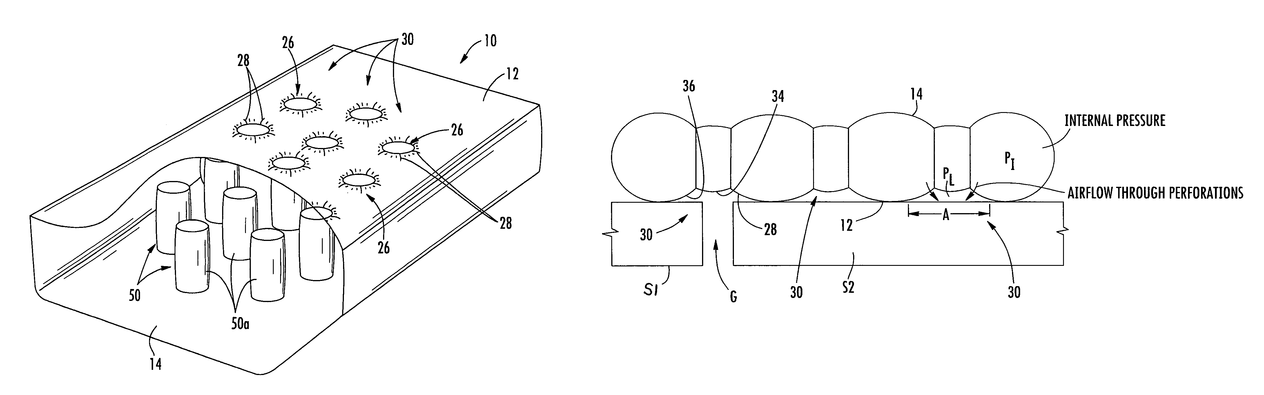
air bearing pallets, when these devices are being transferred between two locations which are separated by a void region.
The air being expelled from the air bearing pallet in order to generate the air film for ease of movement, can become less effective and may be substantially non-functional at this void location due to air pressure loss.
This phenomenon may result in the grounding of load for example a patient, during transfer over this void region.

