Method for judging the reverse connection of a flow sensor and a respiratory mechanics measuring module used therein

a technology of respiratory mechanics and flow sensor, which is applied in the direction of instruments, diagnostic recording/measuring, operating means/releasing devices of valves, etc., can solve the problems of insufficient prevention of erroneous operations by users without engineering knowledge, and the type of connection is not adapted for connecting the gas tubing of flow sensors, etc., to achieve the effect of reducing the manufacturing cost of respiratory mechanics measuring modules, improving efficiency and reducing the manufacturing cos

Active Publication Date: 2011-01-04
SHENZHEN MINDRAY BIO MEDICAL ELECTRONICS CO LTD
View PDF11 Cites 0 Cited by
  • Summary
  • Abstract
  • Description
  • Claims
  • Application Information

AI Technical Summary

Benefits of technology

[0013]2) around the time when the pressure intensity decreases the fastest, the flow has a positive value.
[0019]The first threshold value f1 is set at −2 liters / minute and the second threshold value f2 is set at 3 liters / minute, both of which are useful for eliminating misjudgment caused by tiny and weak interference.
[0025]In comparison with the prior art, the method for judging the reverse connection of a flow sensor and the respiratory mechanics measuring module used in the method according to the present invention achieves great advantageous effect. Specifically, it significantly reduces the manufacturing costs of the respiratory mechanics measuring modules, and it is possible to recognize the reverse connection of a flow sensor at the patient end, leading to improved efficiency as well as reliability and safety of the respiratory mechanics measuring modules.

Problems solved by technology

Current commercially-available patient monitoring systems or anesthetic machines having respiratory mechanics parameters monitoring functions have not been provided with the function for monitoring the installation states of the flow sensors, nor do any technical solutions or relevant patents give clues thereto.
Though this kind of method woks to some extent, it is not sufficient to prevent a user without any engineering knowledge from erroneous operations.
Moreover, this kind of connection is not adapted for connecting the gas tubing of the flow sensors available on the market.
This module provides timely and reliable solutions, but unfortunately is compromised by a relatively high cost.
Moreover it can not address the problem as to the reverse connection of the flow sensors at the patient end either.

Method used


Image

  • Method for judging the reverse connection of a flow sensor and a respiratory mechanics measuring module used therein
  • Method for judging the reverse connection of a flow sensor and a respiratory mechanics measuring module used therein
  • Method for judging the reverse connection of a flow sensor and a respiratory mechanics measuring module used therein

Examples


Embodiment Construction

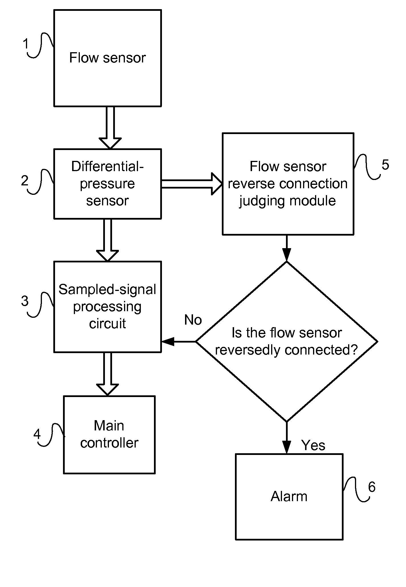
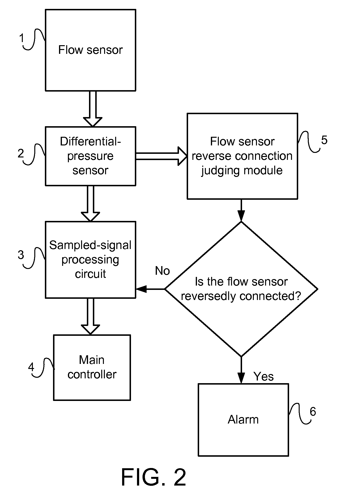
[0033]In the following, preferred embodiments of the respiratory mechanics measuring module and the method for judging the reverse connection of a flow sensor according to the present invention will be described in further details in combination with the accompanying drawings.

[0034]The basic parameters measured by the respiratory mechanics measuring module include the real-time pressure intensity and the real-time flow in the airway. This is how they are measured. The flow sensor senses the absolute pressure intensity (relative to the atmospheric pressure) of the airway and the difference of pressure intensity between two conduits, which difference is then used to scale the flow so as to measure the value of the flow indirectly. Other real-time parameters and parameters concerning the respiratory cycle are all calculated on the basis of these two parameters.

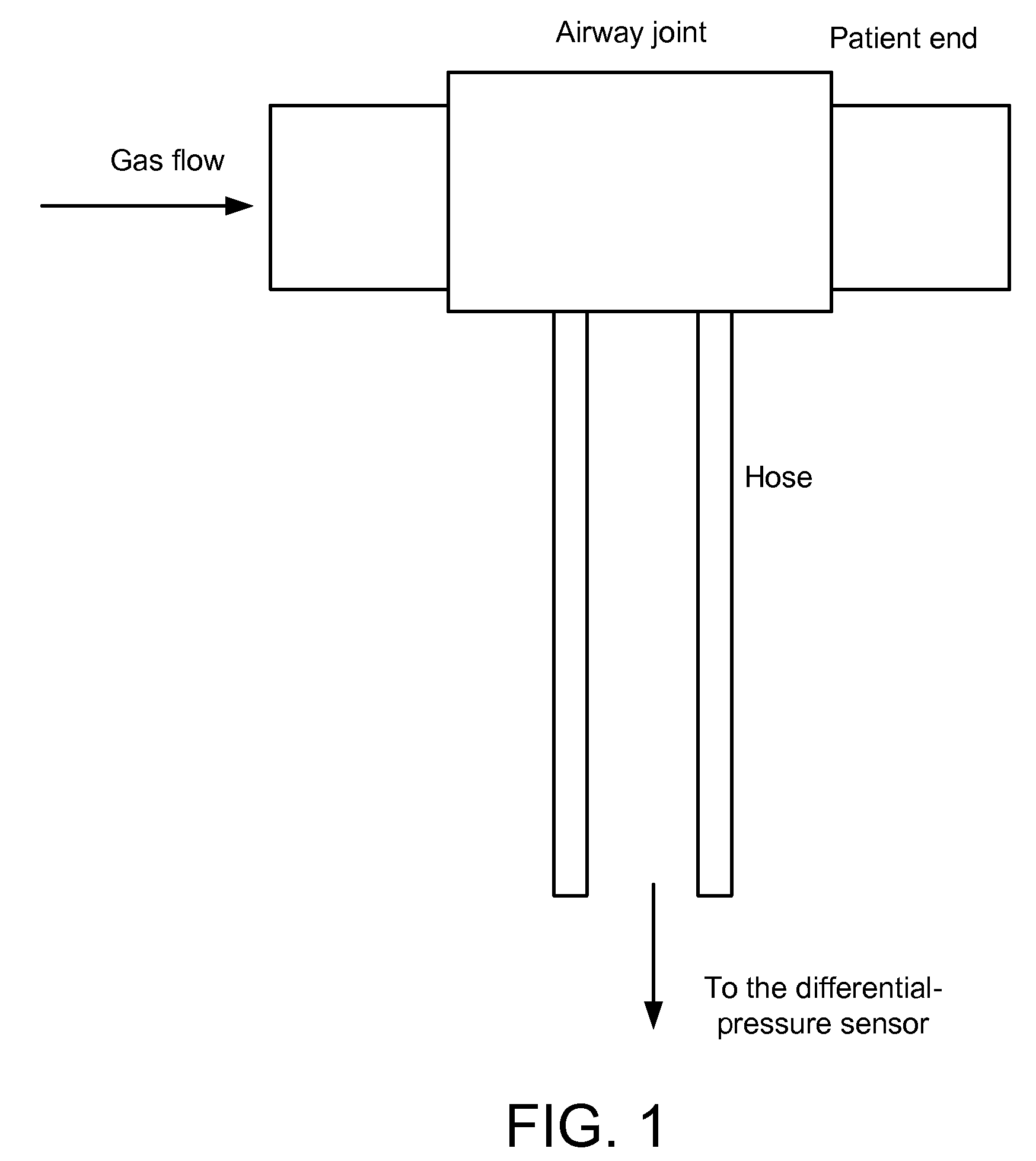
[0035]FIG. 1 is a structural schematic illustration of the flow sensor, in which the two hoses are to the sensor module end, wh...


PUM


Abstract

A respiratory mechanics measuring module includes a flow sensor, a differential-pressure sensor and a sampled-signal processing circuit which are connected in series. The module further includes a flow sensor reverse connection judging module and an alarm. The flow sensor reverse connection judging module judges the reverse connection of the flow sensor. The alarm gives an alarm signal indicating the flow sensor reverse connection to the main controller when the flow sensor reverse connection judging module judges that the flow sensor is reversedly connected.

Description

STATEMENT OF RELATED APPLICATION[0001]The present application claims the priority of the Chinese Patent Application No. 200610033205.5, filed on Jan. 20, 2006, entitled “A Method for Judging the Reverse Connection of a Flow Sensor and a Respiratory Mechanics Measuring Module Used Therein”, which is incorporated herein by reference in its entirety.FIELD OF THE INVENTION[0002]The present invention relates to an apparatus for measuring respiratory flow, more particularly to a respiratory mechanics measuring module and a method for judging the reverse connection (or transposition) of a flow sensor in this module.BACKGROUND OF THE INVENTION[0003]Flow sensors as accessories of the respiratory mechanics modules or the anesthetic machines are the key devices that deliver the information on the airway communicating between the patients and the anesthetic machines to the monitoring modules, and play an important role in monitoring the respiratory mechanics parameters and the working states of...

Claims


Application Information

Patent Timeline
Patent Type & Authority Patents(United States)
IPC IPC(8): A61B5/08A62B9/00A61M16/00A62B27/00G08B5/00G08B3/00
CPCA61M16/08A61B5/087A61M16/0816A61M2016/0036A61M2205/44A61M2205/50
Inventor JIN, WEIHUANG, ZHIWEIYE, JILUN
Owner SHENZHEN MINDRAY BIO MEDICAL ELECTRONICS CO LTD
Why Eureka
Try Eureka