Refueling facility, refueling device, and refueling method

a technology of refueling facility and refueling device, which is applied in the direction of special dispensing means, container discharging from pressure vessels, packaging goods, etc., can solve the problems of battery running out after refueling, vehicle cannot be started after refueling, and the refueling process is complicated, so as to improve the performance stability of moving objects

Active Publication Date: 2011-01-04
TOYOTA JIDOSHA KK
View PDF13 Cites 15 Cited by
  • Summary
  • Abstract
  • Description
  • Claims
  • Application Information

AI Technical Summary

Benefits of technology

[0008]The present invention has been provided in view of the above problems. Therefore, it is an object of the present invention to provide a refueling facility and the like capable of improving the performance stability of a moving object after refueling or the like.

Problems solved by technology

As described above, conventionally there has been a problem that refueling requires a complicated work.
Incidentally, when the fuel cell vehicle is refueled, there is such a problem that a battery runs out after the refueling or the like due to power consumption of power consuming devices (for example, a lighting device, an air conditioner, a temperature control mechanism, and other auxiliary machines mounted on the vehicle) during the refueling in addition to the above problem.
Due to large power consumption caused by the temperature control mechanism, the battery runs out if the temperature control mechanism continues to be operated during the refueling, which leads to such a problem that the vehicle cannot be started after the refueling.

Method used


Image

  • Refueling facility, refueling device, and refueling method
  • Refueling facility, refueling device, and refueling method
  • Refueling facility, refueling device, and refueling method

Examples


first embodiment

A. First Embodiment

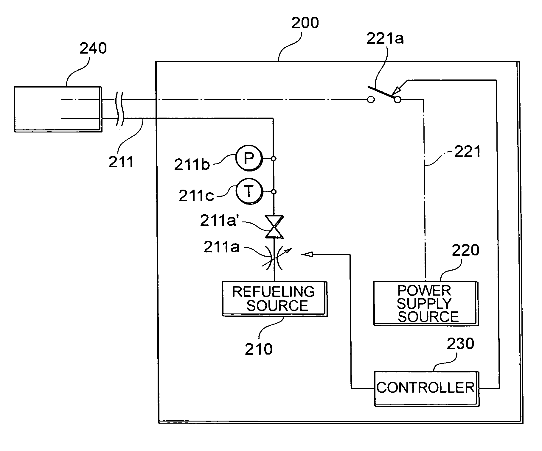
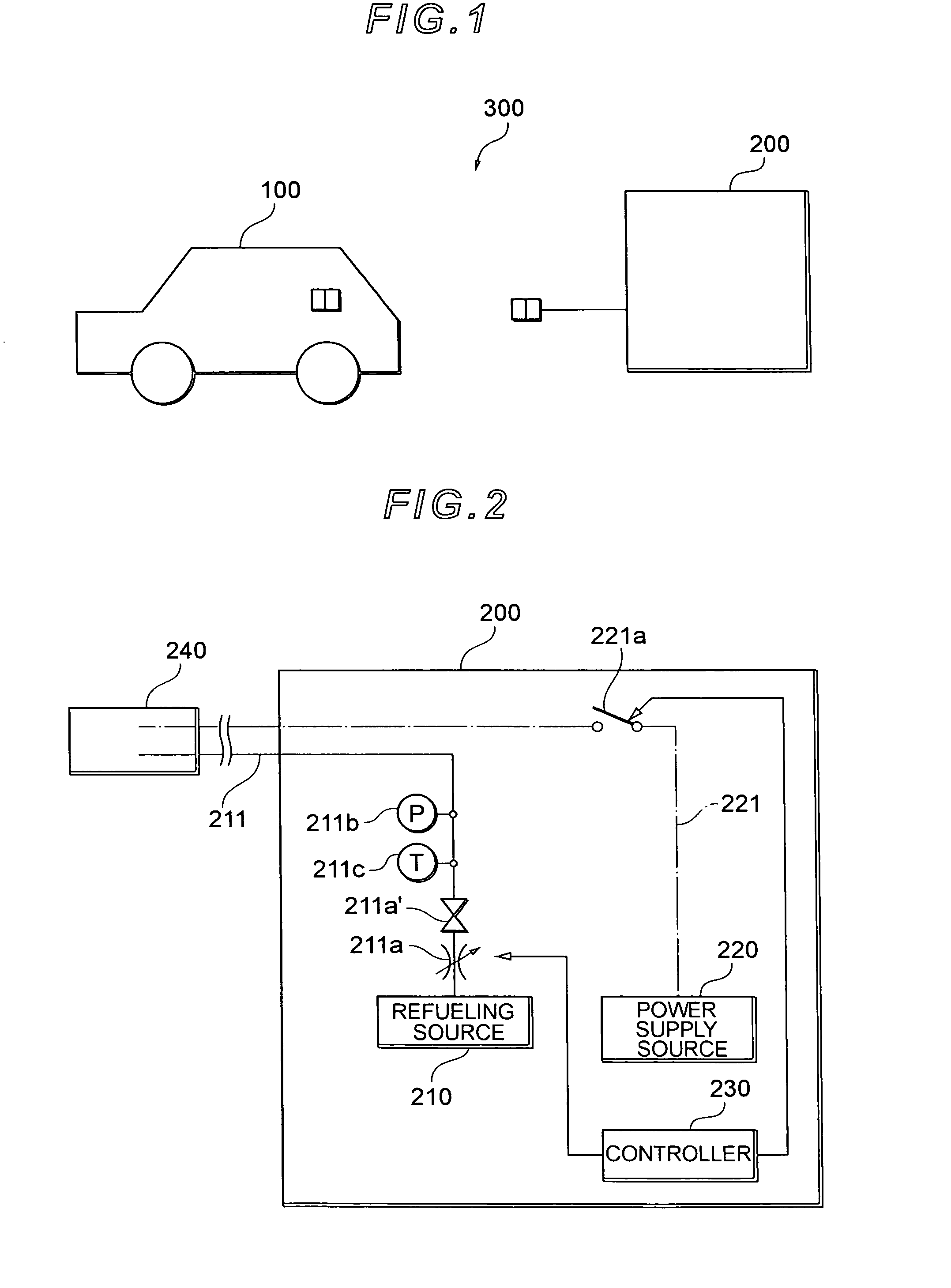
[0034]Referring to FIG. 1, there is shown the configuration of a refueling system 300 according to a first embodiment. The refueling system 300 includes a fuel cell vehicle 100 running on hydrogen and a refueling facility 200 for supplying fuel and power to the fuel cell vehicle 100. While the fuel cell vehicle running on hydrogen is exemplified in this embodiment, the present invention is also applicable to a fuel cell vehicle running on ethanol or the like. In addition, the present invention is also applicable to a hybrid car or a gasoline car similarly, as well as the fuel cell vehicle. In other words, the fuel in the present invention can be gas fuel (hydrogen gas or natural gas) or liquid fuel (gasoline, ethanol, light oil, or liquid hydrogen). Furthermore, while a vehicle (moving object) is assumed as a target to which the refueling system 300 is applied in this embodiment, the present invention is applicable to all kinds of movable bodies such as, for examp...

second embodiment

B. Second Embodiment

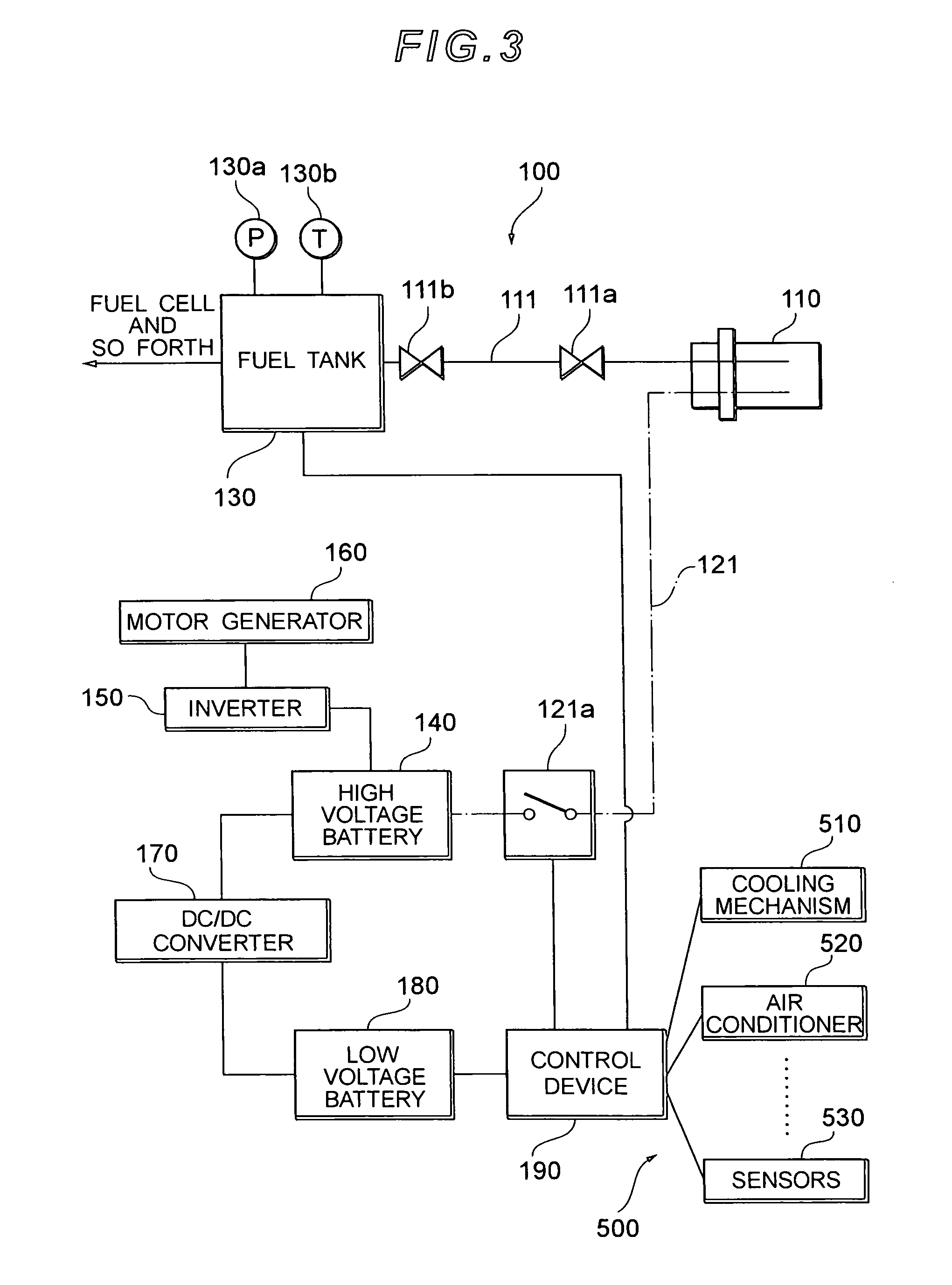
[0051]Referring to FIG. 5, there is shown the configuration of a refueling facility 200′ according to a second embodiment. Referring to FIG. 6, there is shown the configuration of a refueling device (fuel device) of a fuel cell vehicle 100′ according to the second embodiment. Regarding the refueling facility 200′ shown in FIG. 5 and the fuel cell vehicle 100′ shown in FIG. 6, the same reference numerals are used to denote corresponding parts to those of the refueling facility 200 shown in FIG. 2 and those of the fuel cell vehicle 100 shown in FIG. 3 and their detailed description is omitted here.

[0052]The refueling facility 200′ is provided with a status signal line 21 for sending or receiving a status signal to or from the fuel cell vehicle 100. One end of the status signal line 21 is connected to a controller 230 and the other end (the forward end of the status signal line 21) is connected to a supply connector 240. In other words, a refueling connector, a powe...


PUM

PropertyMeasurementUnit
poweraaaaaaaaaa
state of chargeaaaaaaaaaa
electric energyaaaaaaaaaa

Abstract

A refueling facility (200) according to the present invention comprises a refueling source (210) for refueling a fuel cell vehicle with fuel, a power supply source (220) for supplying power to the fuel cell vehicle, and a controller (230) for controlling refueling and power supply from the refueling facility (200) to the fuel cell vehicle. The forward end of a refueling path (211) and that of a power supply path (221) are integrated into a supply connector (240). The refueling and the power supply are achieved by connecting the supply connector (240) to a fuel receptacle (110) of the fuel cell vehicle.

Description

[0001]This is a 371 national phase application of PCT / JP2005 / 013210 filed 12 Jul. 2005, claiming priority to Japanese Patent Application No. 2004-206110 filed 13 Jul. 2004, the contents of which are incorporated herein by reference.BACKGROUND[0002]The present invention relates to a refueling facility for supplying fuel, a refueling device to be refueled by the refueling facility, and a refueling method.[0003]Conventionally, there have been suggested various fuel cell vehicles driven using electric energy, which is output from a fuel cell. This type of fuel cell vehicle is configured to be refueled with hydrogen or other fuels through a fuel hose or the like from a refueling facility.[0004]In order to refuel the fuel cell vehicle, it is necessary to connect the refueling facility to the fuel cell vehicle using a refueling connector of the fuel hose and to connect them to each other using an electrical signal connector to send or receive a signal or the like that indicates the state o...

Claims


Application Information

Patent Timeline
Patent Type & Authority Patents(United States)
IPC IPC(8): B65B3/04B67D7/04B67D7/06
CPCB60L1/003B60L11/1803B60L11/1887B60L11/1892B60L11/1894F17C5/007F17C5/02F17C5/06F17C7/00F17C2205/037F17C2221/012F17C2221/033F17C2227/0341F17C2250/032F17C2250/0439F17C2250/0478F17C2250/0626F17C2270/0105F17C2270/0139F17C2270/0178F17C2270/0184F17C2270/0189Y02E60/321Y02T90/34B60L50/51B60L58/40B60L58/33B60L58/34Y02E60/32Y02T90/40Y02T10/70B60L50/75
Inventor IIDA, YASUYUKI
Owner TOYOTA JIDOSHA KK
Why Eureka
Try Eureka