Rolled tape dispenser

a dispenser and tape technology, applied in the field of dispensers, can solve the problems of high cost of components, long reaches of tape being trampled, waste, etc., and achieve the effect of strengthening its strength

Active Publication Date: 2011-01-04
CHAGRINOVATIONS LLC
View PDF48 Cites 25 Cited by
  • Summary
  • Abstract
  • Description
  • Claims
  • Application Information

AI Technical Summary

Benefits of technology

[0007]In some embodiments, a cover that is removably connected to the L-shaped body of the dispenser—a cover that overlies a portion of the shorter leg and the cutter blade supported by the shorter leg—also is formed from injection molded plastics material as a one-piece structure, and defines a projection that extends at least a short distance along and engages one side of a spindle-carried tape roll in much the same manner that the longer leg extends along and engages a much longer portion of the other side of the spindle-carried tape roll—an arrangement that also assists in maintaining the orderly form of rolls of tape that are supported on the spindle of the dispenser. In place of, or in addition to the provision of a cover-defined projection that extends at least a short distance along a side of a spindle-supported tape roll (so that the roll is engaged near its periphery on one side by the cover-defined projec

Problems solved by technology

Previously proposed rolled tape dispensers that were intended to be belt or strap supported so that a wearer could dispense either a continuous length of tape or a series of relatively short lengths of tape typically presented disadvantages resulting from complexity of design, high cost of component parts, inability to accommodate one-handed dispensing when strap or belt supported alongside the thigh or hip of a wearer, and operational characteristics that may change detrimentally as the diameter of a tape roll being dispense

Method used


Image

  • Rolled tape dispenser
  • Rolled tape dispenser
  • Rolled tape dispenser

Examples


Embodiment Construction

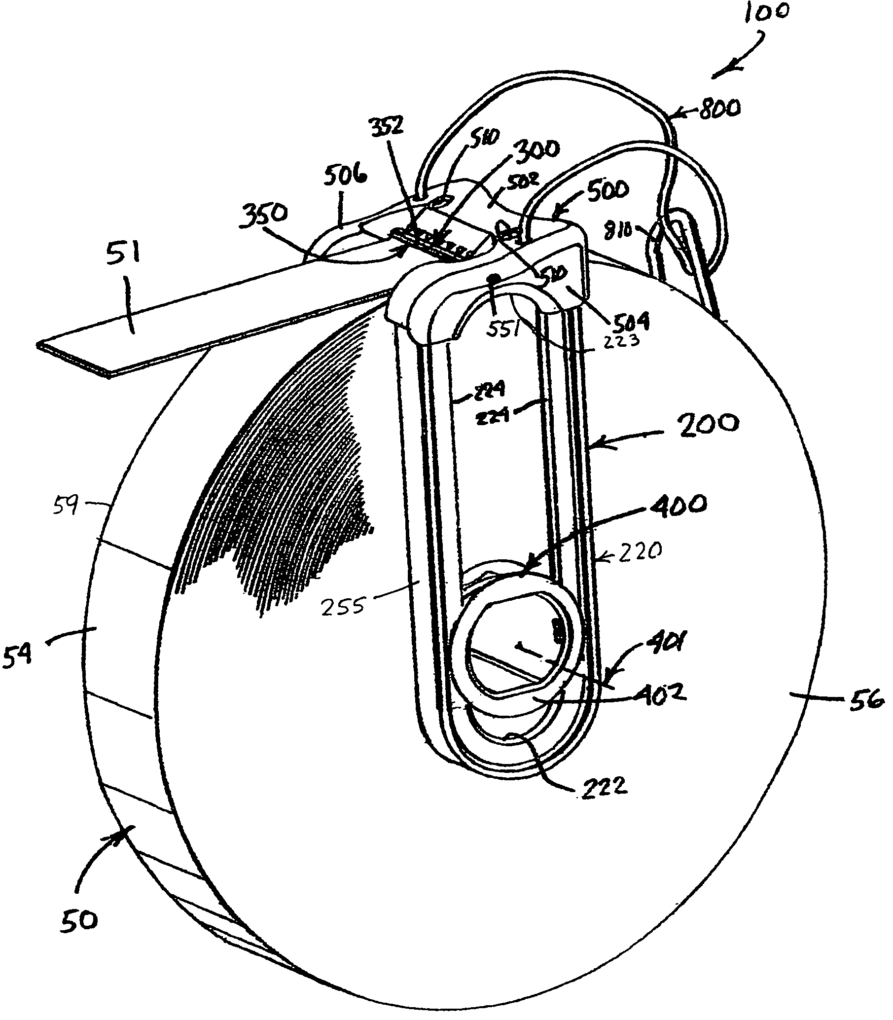
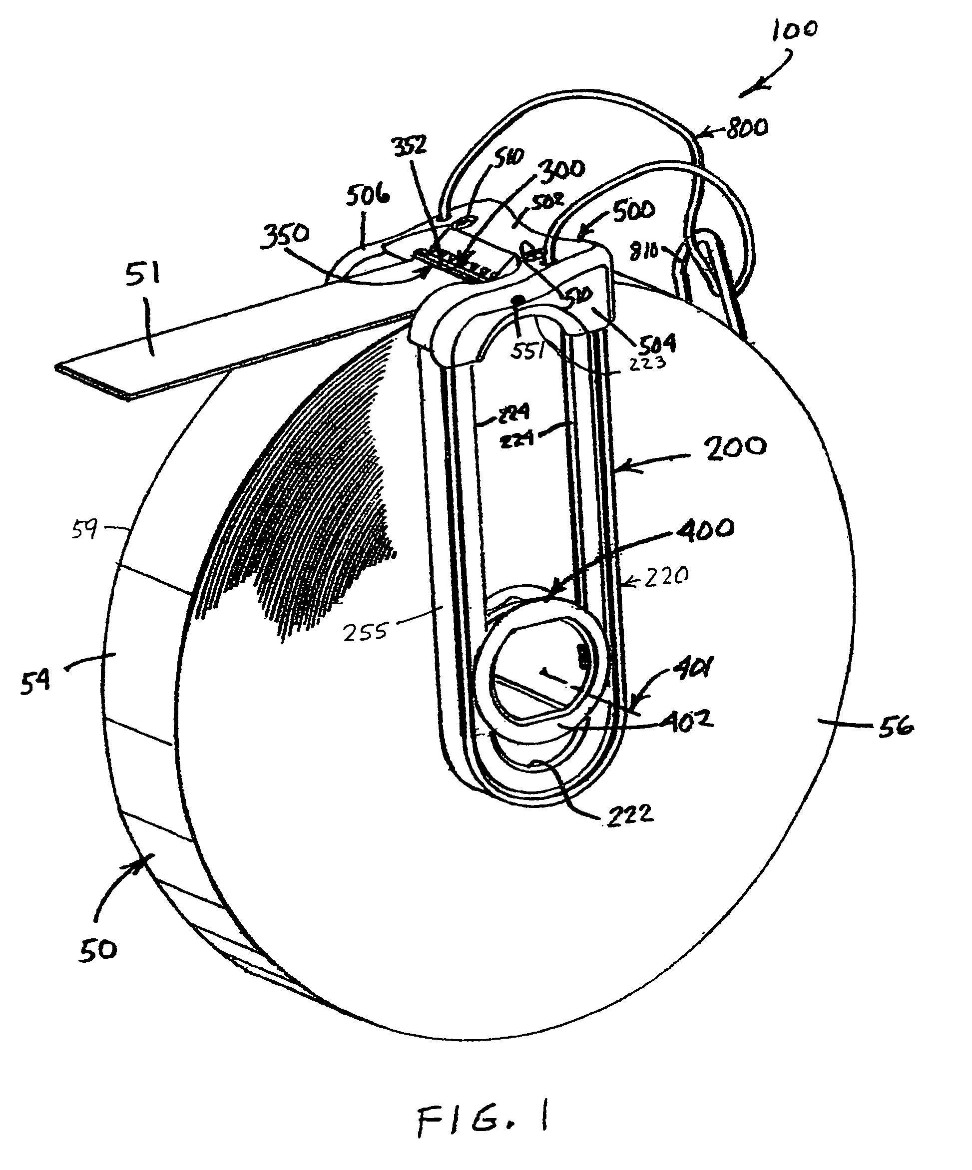
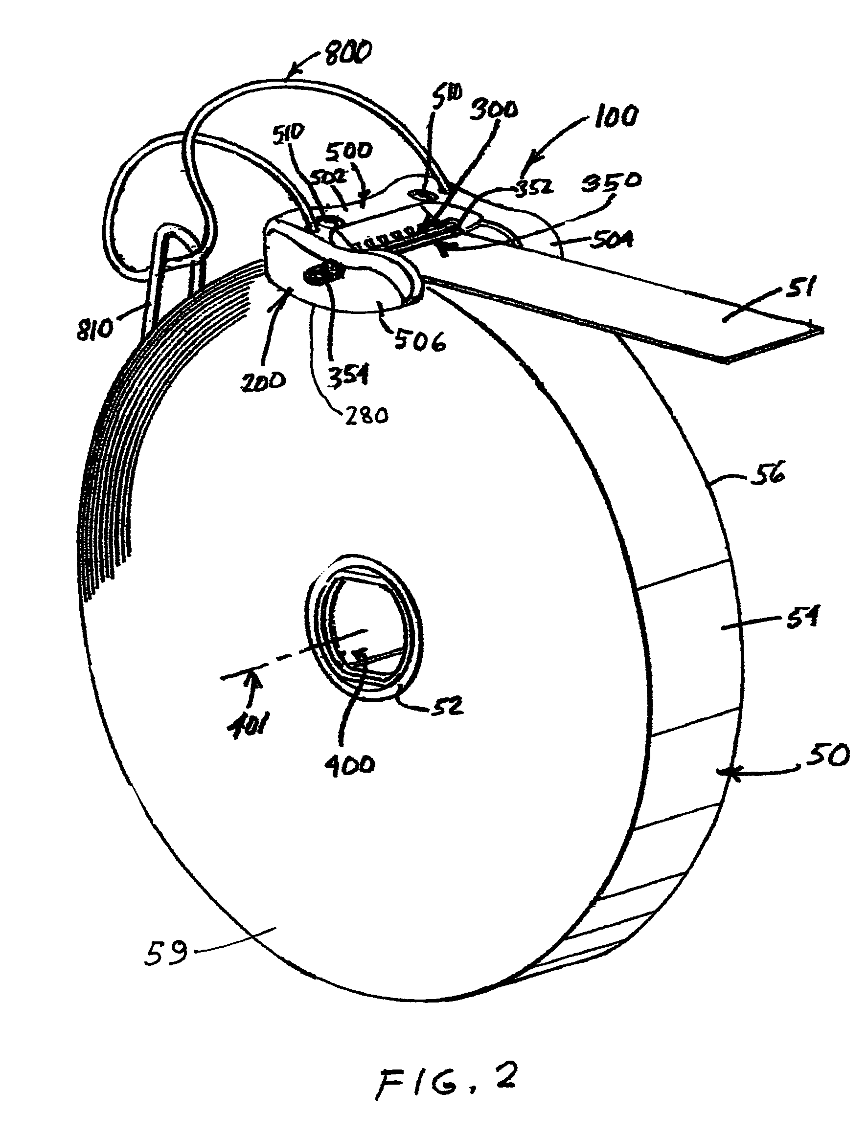
[0031]Referring to FIGS. 1-3, a rolled tape dispenser embodying features of the present invention is indicated generally by the numeral 100. The dispenser 100 has a body 200 that movably supports a spindle 400 which is shown in FIG. 2 extending into a hollow central core 52 of the relatively full-sized tape roll 50, and which is shown in FIG. 3 extending into a hollow central core 52A of a less-full, somewhat depleted tape roll 50A—by which arrangements, one or the other of the tape rolls 50, 50A may be mounted on the dispenser 100.

[0032]In FIGS. 1 and 2 the depicted full-sized tape roll 50 has a larger diameter than the somewhat depleted form of the tape roll 50A that is shown in FIG. 3. What FIGS. 1 and 2 show is how a short length of tape 51 can be pulled from the roll 50. What FIG. 3 shows is how a short length of tape 51A can be severed from the roll 50A by pulling a portion of the tape length 51A across the sharpened edge 302 of the cutter blade 300 of the dispenser 100 at a t...


PUM


Abstract

A rolled tape dispenser that has a generally L-shaped body with a relatively short leg that supports a cutter blade and cover to extend transversely across the width of the cylindrical outer surface of a roll of tape, and a longer leg configured to extend along one of two opposite sides of the roll of tape. A spindle is configured to be inserted into a hollow central core of the roll of tape has an end region slidably connected to the longer leg for movement along the length of the longer leg. A resilient member connected to the body biases the spindle toward the cutter blade so that a roll of tape carried on the spindle has its generally cylindrical outer surface biased into engagement with the cutter blade, or, more preferably, into engagement with a thin portion of the shorter leg that underlies the cutter blade.

Description

BACKGROUND OF THE INVENTION[0001]The present invention relates to a dispenser for a wide variety of types of tape sold in rolls, including several kinds of tape that are relatively difficult to hold and / or to dispense, for example, relatively thick woven fabric tape formed from synthetic material in fiber form such as polyamide, polyester and polyolefin polymers and the like such as Nylon, Dacron and Kevlar that carries no adhesive backing and therefor has a low coefficient of friction that renders the tape so slippery that the tape tends to unroll and slide out of the orderly coiled configuration in which a roll of tape is sold unless restrained against unrolling and uncoiling—a dispenser having portions that engage three surfaces of a coiled roll of tape to maintain the orderly configuration of the tape roll during dispensing—a dispenser that permits tape to be unrolled and dispensed as needed for continuous application or that permits desired lengths of tape to be severed from th...

Claims


Application Information

Patent Timeline
IPC IPC(8): B26F3/02
CPCB65H35/0026Y10T225/268Y10T225/269
Inventor TAYLOR, CURTIS P.MIKA, STEPHEN E.
Owner CHAGRINOVATIONS LLC
Why Eureka
Try Eureka