Blood vessel endothelium function evaluating apparatus provided with an electronic control device

a technology function evaluation, which is applied in the field of blood vessel image measuring apparatus, can solve the problems of insufficient evaluation of the function of blood vessel endothelium, limits in the accuracy of blood vessel diameter measurement, etc., and achieves clear and accurate transverse cross-section image

Inactive Publication Date: 2011-01-04
UNAX CORP
View PDF29 Cites 8 Cited by
  • Summary
  • Abstract
  • Description
  • Claims
  • Application Information

AI Technical Summary

Benefits of technology

[0007]It is therefore an object of the present invention to provide a blood-vessel-image measuring apparatus that can obtain a highly accurate diameter of a blood vessel.
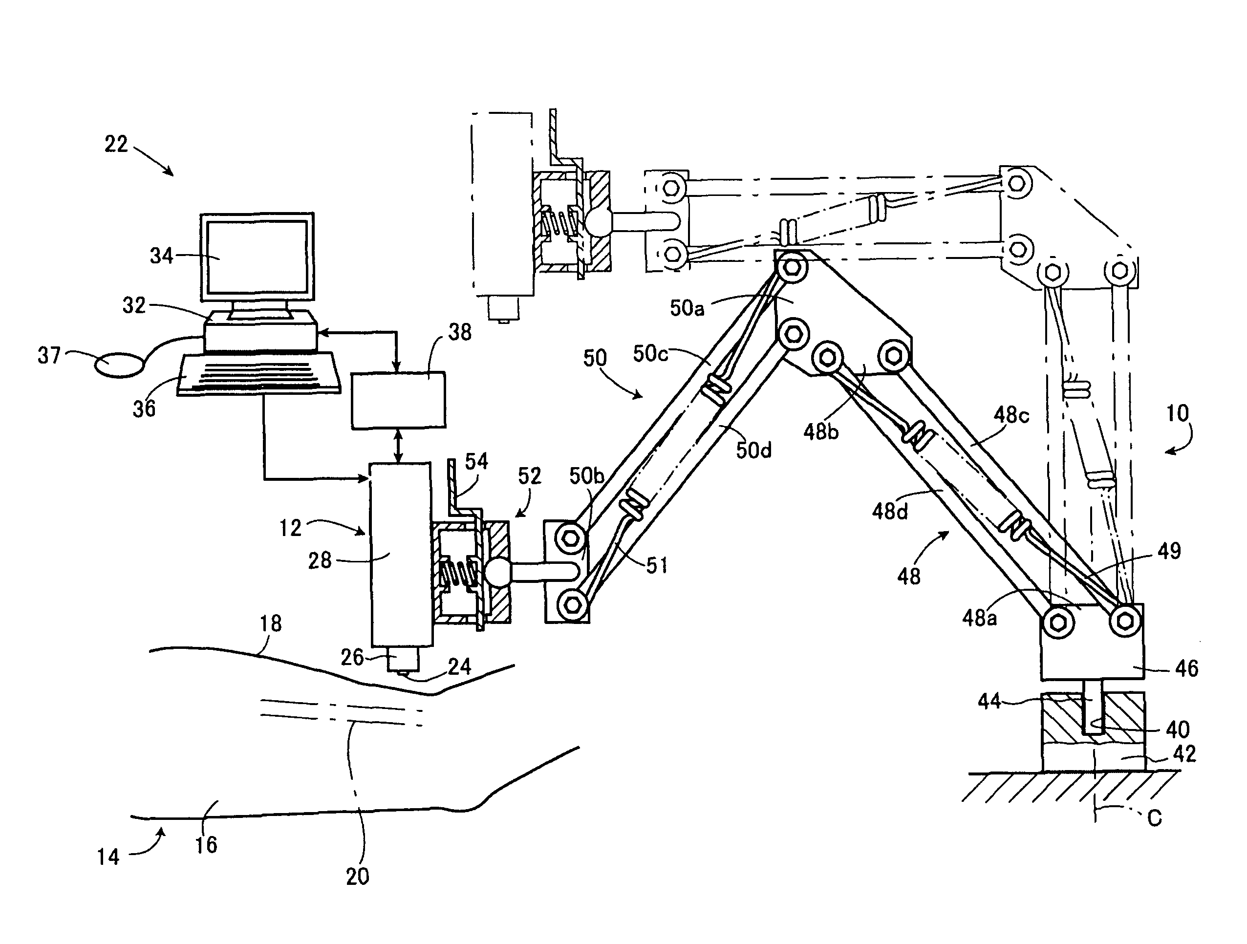
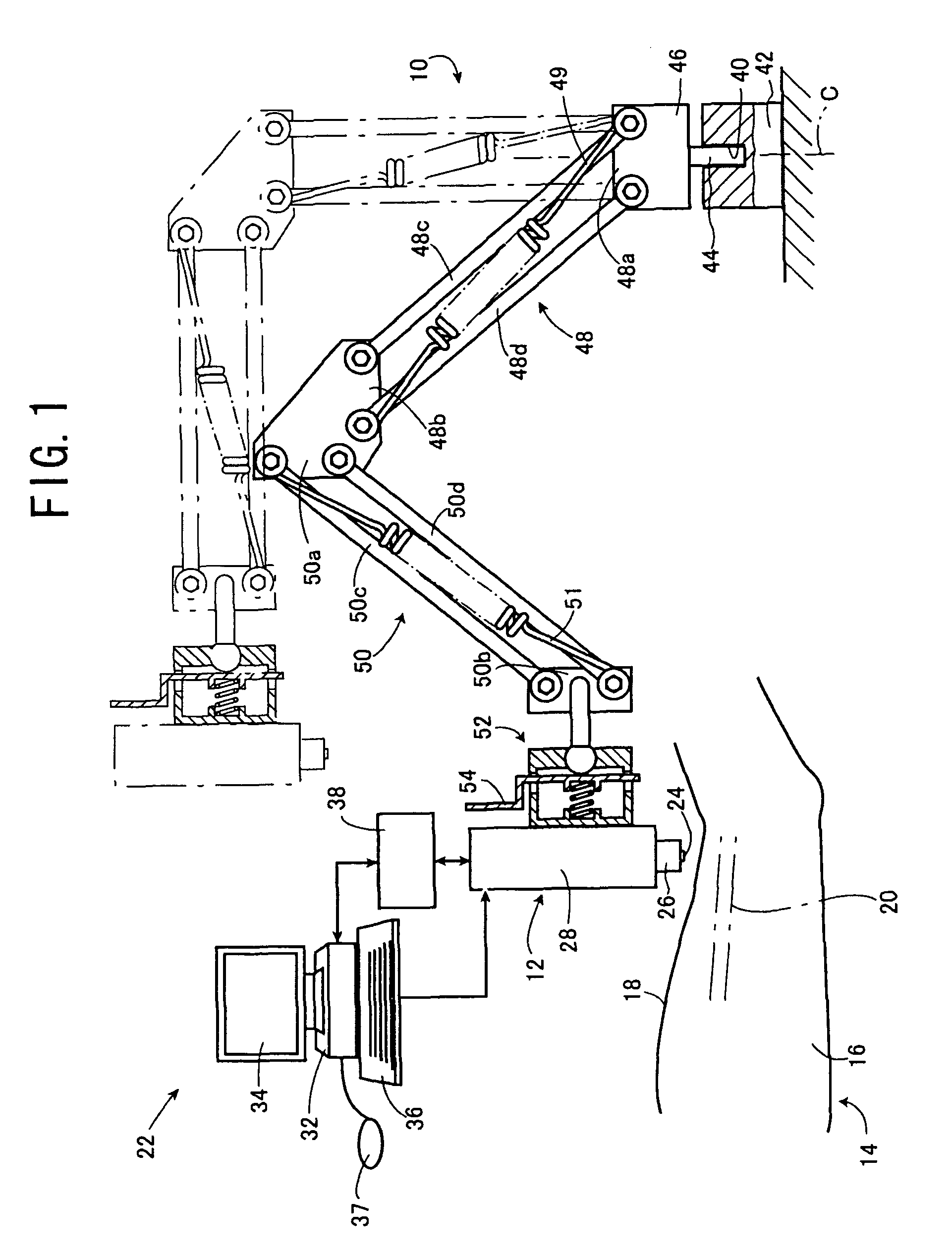
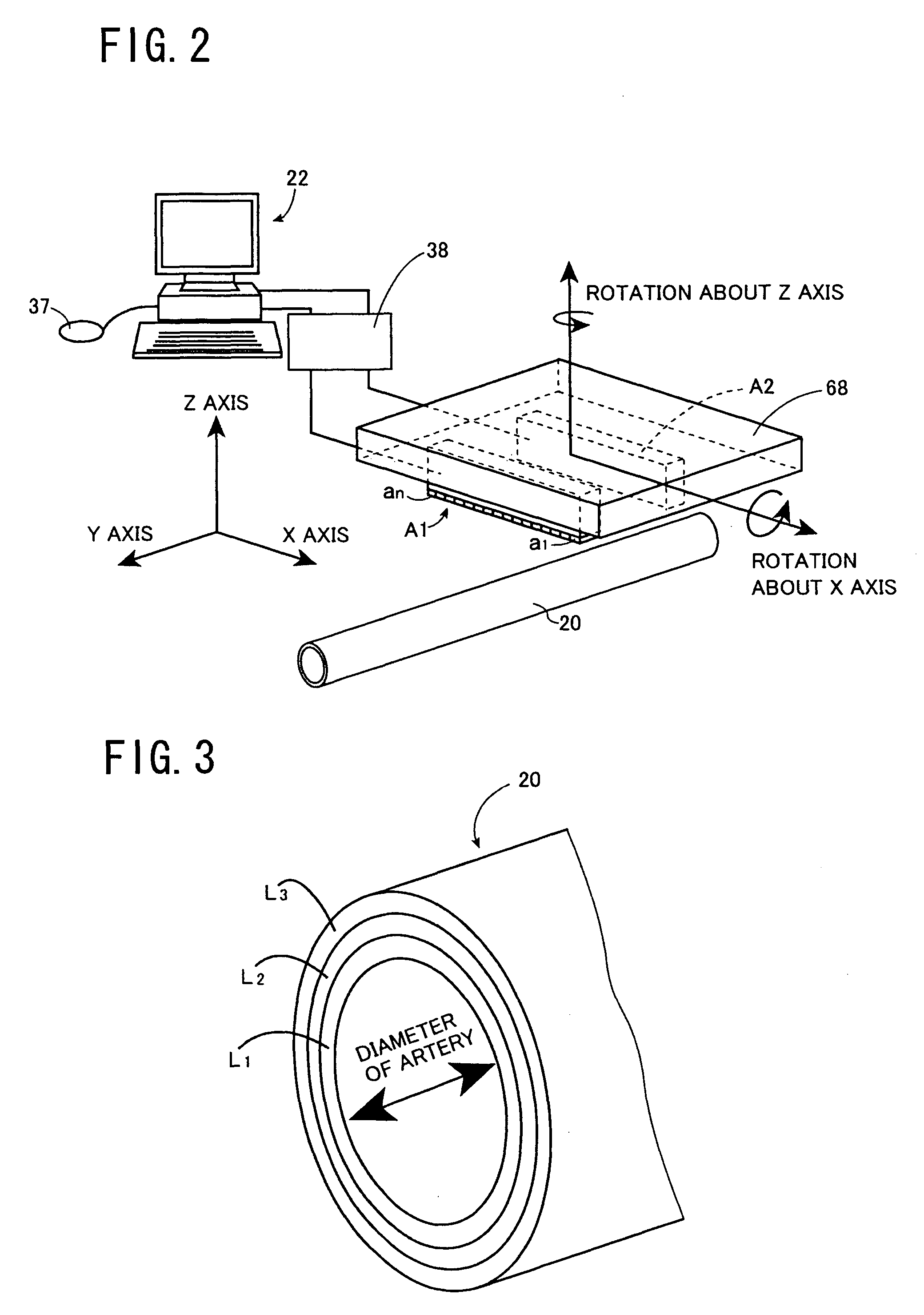
[0023]In the blood-vessel-image measuring apparatus according to the eighth mode of the present invention, the ultrasonic probe includes the main frame adapted to be placed on the skin of the living being, and the y-axis supporting device that is supported by the main frame and that supports the ultrasonic array such that the ultrasonic array is rotatable about the y axis perpendicular to the direction of arrangement of the ultrasonic transducers; the image displaying device displays the image of the blood vessel, including the endothelium, obtained by the ultrasonic array; and the input device is manually operable to adjust the rotation of the ultrasonic array, supported by the y-axis supporting device, about the y axis. Therefore, the input device is manually operated till the emission surface of the ultrasonic probe is so inclined relative to the surface of the skin opposed to the emission surface as to prevent the multiple reflection, or the ghost image of the endothelium produced by the multiple reflection, and accordingly a highly clear and accurate transverse cross-section image of the endothelium (i.e., the inner layer) of the blood vessel can be obtained.

Problems solved by technology

However, since the accuracy of measurement of the blood-vessel diameter has limits, the accuracy of evaluation of the function of blood-vessel endothelium has not been sufficiently high.

Method used


Image

  • Blood vessel endothelium function evaluating apparatus provided with an electronic control device
  • Blood vessel endothelium function evaluating apparatus provided with an electronic control device
  • Blood vessel endothelium function evaluating apparatus provided with an electronic control device

Examples


second embodiment

[0077]FIG. 19 is a flow chart representing relevant steps of an operation of an electronic control device 32 employed in the First, at Step S11, ultrasonic-beam emission and scanning are started. That is, the two ultrasonic arrays A1, A2 emit the respective convergent ultrasonic beams to scan respective portions of the blood vessel 20 and obtain respective cross-section images G1, G2 shown in an upper portion of FIG. 20. Subsequently, at Step S12, the control device 32 calculates a distance, e, between the blood vessel 20 and a left side of the first rectangular display area displaying the cross-section image G1, and a distance, f, between the blood vessel 20 and a right side of the first rectangular display area, and operates the x-axis actuator 106 to change, by a pre-set amount, a position of the ultrasonic arrays A1, A2 with respect to the x-axis direction, in a direction to decrease a difference of the two distances e, f. Step S12 is followed by Step S13 to judge whether the t...

third embodiment

[0082]FIG. 24 is a flow chart representing relevant steps of an operation of an electronic control device 32 employed in the First, at Step S21, ultrasonic-beam emission and scanning are started. That is, the two ultrasonic arrays A1, A2 emit respective convergent ultrasonic beams to scan respective portions of the blood vessel 20 and obtain respective ultrasonic cross-section images G1, G2, as shown in an upper portion of FIG. 25. The ultrasonic cross-section images G1, G2 are displayed by the monitor-image displaying device 34. Subsequently, at Step S22, if the two short-axis images G1, G2, displayed by the displaying device 34, have respective ghost images L1′ of the inner layer L1 that are caused by the multiple reflection produced between the skin surface 18 and the blood vessel 20, a rotation angle of the ultrasonic arrays A1, A2 about the y axis is changed by a predetermined angle in a direction to solve the multiple reflection. Then, at Step S23, whether the two short-axis ...

first embodiment

[0086]In the first embodiment shown in FIGS. 1 through 14, the rotation of the two ultrasonic arrays A1, A2 about the x axis is automatically carried out at Steps S2 and S3 of FIG. 10; and the rotation of the ultrasonic arrays A1, A2 about the z axis is automatically carried out at Steps S4 and S5 of FIG. 10. However, the rotation of the ultrasonic arrays A1, A2 about each of the x axis and the z axis may be controlled in a manual operation.

[0087]In a modified form of the first embodiment, Step S2 of FIG. 10 is replaced with a step where the monitor-image displaying device 34 displays, as shown in an upper portion of FIG. 27, respective ultrasonic cross-section images G1, G2, obtained by the two ultrasonic arrays A1, A2, such that respective center positions of the blood vessel 20 in the z axis are indicated or designated by respective symbols, C1, C2, and an arrow, J, representing a rotation direction, about the x axis, in which the x-axis rotating device 70 is rotated to zero the ...


PUM


Abstract

An apparatus for measuring a short-axis image of a blood vessel under a skin of a living being, the apparatus including an ultrasonic probe including an ultrasonic array which has a plurality of ultrasonic transducers arranged in one direction in an emission surface and which emits, from the emission surface, an ultrasonic beam toward the blood vessel, the ultrasonic probe additionally including a main frame which is adapted to be placed on the skin of the living being, an x-axis supporting device which is supported by the main frame and which supports the ultrasonic array such that the ultrasonic array is rotatable about an x axis parallel to the direction of arrangement of the ultrasonic transducers in the emission surface, and an x-axis control device which controls a posture of the ultrasonic array supported by the x-axis supporting device such that in a y-z plane, the emission surface of the ultrasonic array is parallel to the blood vessel.

Description

[0001]The present application is based on Japanese Patent Application No. 2005-247690 filed on Aug. 29, 2005, the contents of which are incorporated herein by reference.BACKGROUND OF THE INVENTION[0002]1. Field of the Invention[0003]The present invention relates to a blood-vessel-image measuring apparatus that measures, with an ultrasonic probe including an ultrasonic array that emits, from an emission surface thereof, an ultrasonic beam, an image including a blood vessel that underlies a skin of a living being and has an endothelium.[0004]2. Related Art Statement[0005]There has been proposed a blood-vessel-image measuring apparatus that measures, with an ultrasonic array that is lightly contacted with a skin of a living being (e.g., a living person) via a coupling agent such as a jelly and emits an ultrasonic beam toward the skin, an image including a blood vessel underlying the skin. This measuring apparatus is disclosed by, e.g., Japanese Patent Application Publication No. 2003-2...

Claims


Application Information

Patent Timeline
Patent Type & Authority Patents(United States)
IPC IPC(8): A61B8/00
CPCA61B5/02007A61B8/14A61B8/4218A61B5/1075
Inventor IIKUBO, KATSUSHISASAKI, HIDEHITOSUZUKI, HIDENORITSUKAHARA, HIROMASAHARADA, CHIKAOHIRANO, HITOSHIMASUDA, HIROSHI
Owner UNAX CORP
Why Eureka
Try Eureka