
Non-linear control techniques for improving transient response to load current step change

a step change and load current technology, applied in the field of electric circuits, can solve the problems of regulators not being able to respond fast, large step change in load current within a relatively short period of time, not always the case in real world conditions, etc., and achieve the effect of limited linear control bandwidth

Active Publication Date: 2011-01-04
SEMICON COMPONENTS IND LLC
View PDF27 Cites 53 Cited by
  • Summary
  • Abstract
  • Description
  • Claims
  • Application Information

AI Technical Summary

Benefits of technology

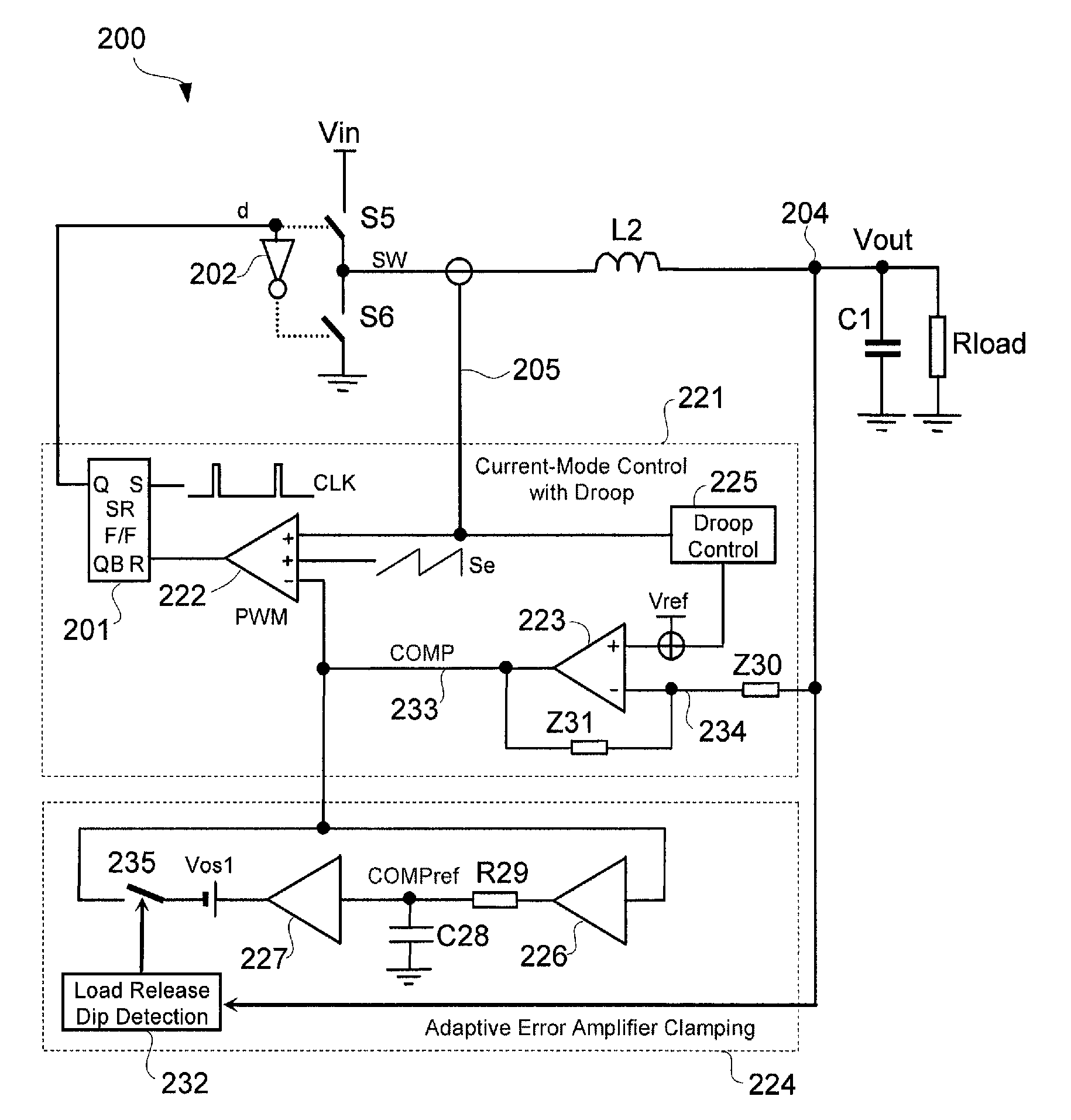
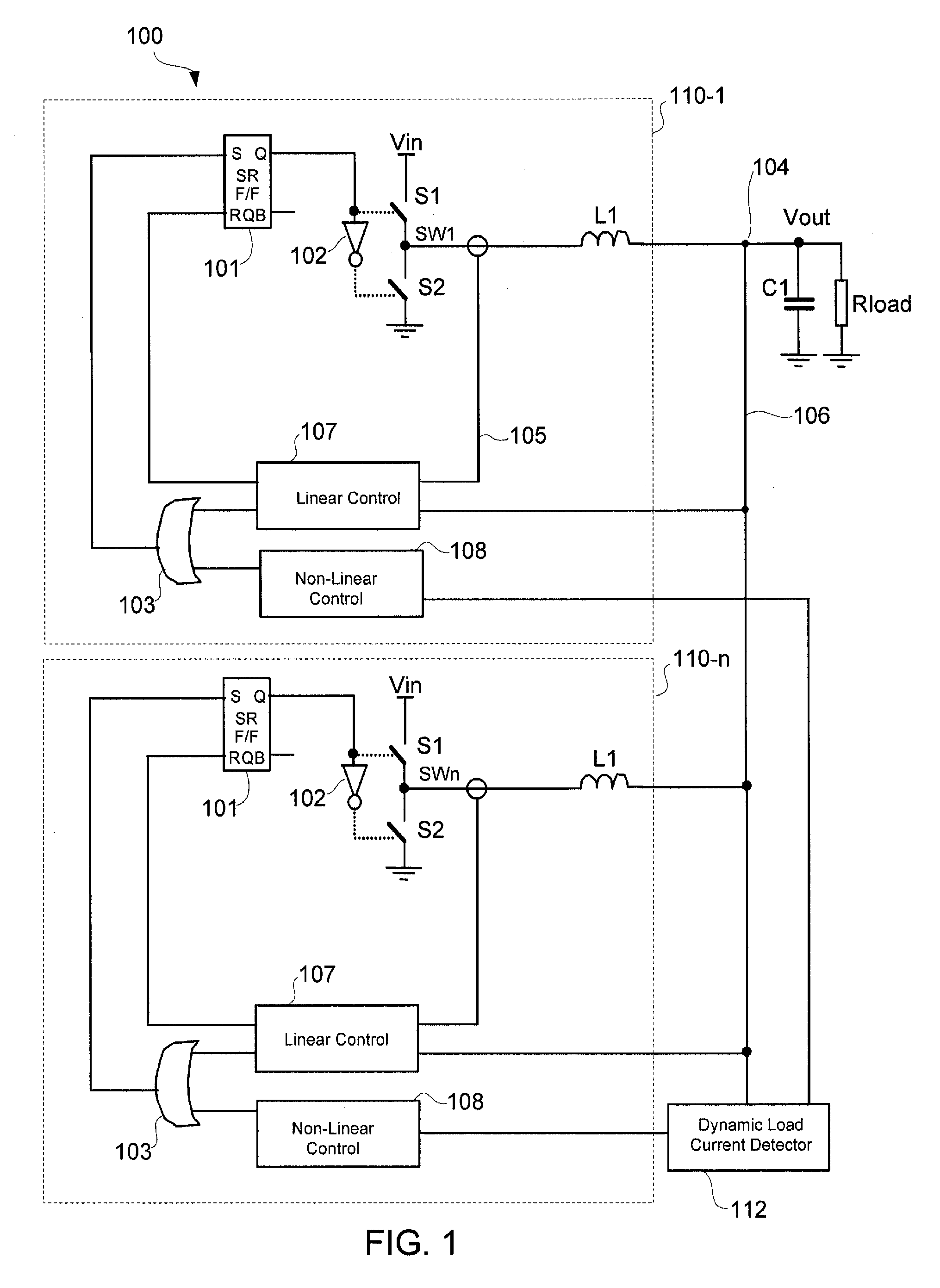
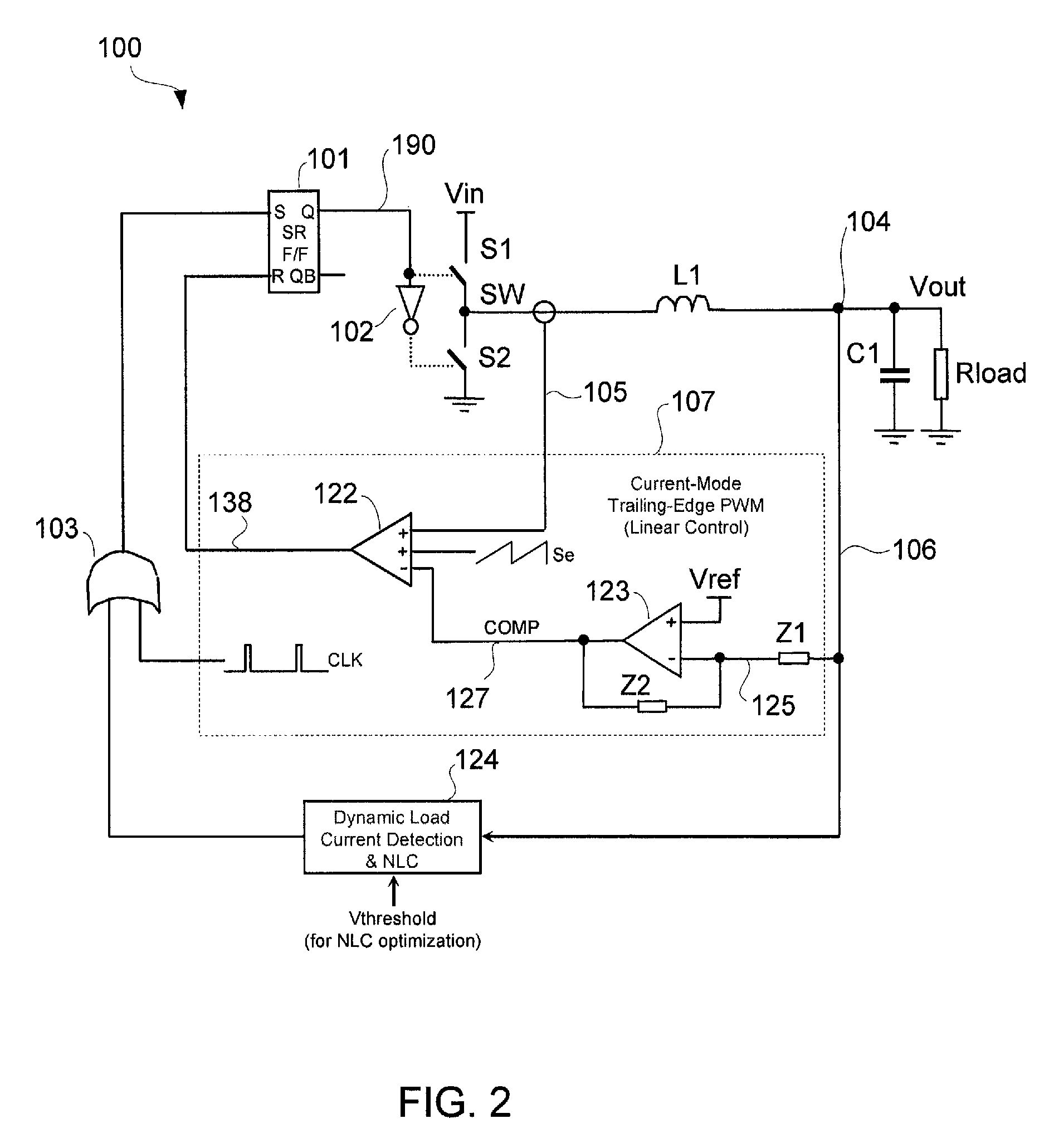
[0006]A voltage regulator may be configured to detect variation in load current and control transient response when the load current varies at high slew rates and / or high repetition rates. A linear control circuit may be employed to regulate the output voltage within its tolerance band. Upon detection of fast load current step-up change, a non-linear control circuit may be used to expand the limited linear control bandwidth. The fast load current step-up change may be detected by comparing an output voltage of the regulator to a feedback input of an error amplifier of the linear control circuit. The output of the error amplifier may be adaptively clamped to prevent output voltage ring-back when using the non-linear control circuit and / or to control load release dip. Output voltage overshoot may be controlled by turning OFF a top switch that charges the output capacitor well before the inductor current reaches zero.

Problems solved by technology

However, this is not always the case in real world conditions.
For example, a microprocessor waking out of “sleep” mode may activate a large number of dormant circuits, resulting in a large step change in load current within a relatively short period of time.
In these cases, the regulator may not be able to respond fast enough to maintain the output voltage VOUT within regulation.

Method used


Image

  • Non-linear control techniques for improving transient response to load current step change
  • Non-linear control techniques for improving transient response to load current step change
  • Non-linear control techniques for improving transient response to load current step change

Examples


Embodiment Construction

[0030]In the present disclosure, numerous specific details are provided, such as examples of circuits, components, and methods, to provide a thorough understanding of embodiments of the invention. Persons of ordinary skill in the art will recognize, however, that the invention can be practiced without one or more of the specific details. In other instances, well-known details are not shown or described to avoid obscuring aspects of the invention.

Non-Linear Control

[0031]Load current is the electrical current drawn by the load from the regulator. For purposes of the present disclosure, a load current has a high slew rate when it has a slew rate of around 100 A / μs and above, and has a high repetition rate when its repetition rate is around 100 kHz and above. A load current step change is a fast change in load current. A step change may be a step-up change where the load current rapidly changes from low to high, or a step-down change where the load current rapidly changes from high to l...


PUM


Abstract

A voltage regulator may be configured to detect variation in load current and control transient response when the load current has a high slew rate or varies at high repetition rates. A linear control circuit may be employed to control charging of an output capacitor and a load of the regulator. Upon detection of high load current step-up change at high slew rates, a non-linear control circuit may be activated. The fast load current step change may be detected by comparing an output voltage of the regulator to a feedback input of an error amplifier of the linear control circuit. The output of the error amplifier may be clamped to prevent output voltage ring-back when using the non-linear control circuit or to control load release dip. Output voltage overshoot may be controlled by turning OFF a top switch that charges the output capacitor before the inductor current becomes zero.

Description

BACKGROUND OF THE INVENTION[0001]1. Field of the Invention[0002]The present invention relates generally to electrical circuits, and more particularly but not exclusively to voltage regulators.[0003]2. Description of the Background Art[0004]A voltage regulator generates a regulated output voltage VOUT from an input voltage VIN. Ideally, the voltage regulator maintains the output voltage VOUT within regulation despite varying load current. However, this is not always the case in real world conditions. One instance is when the load current is varying at high slew rates and high repetition rates, which may be as much as 1000 A / μs slew rate and up to 1 MHz repetition rate. For example, a microprocessor waking out of “sleep” mode may activate a large number of dormant circuits, resulting in a large step change in load current within a relatively short period of time. As another example, the current drawn by a microprocessor may toggle at high repetition rates when running video games. In ...

Claims


Application Information

Patent Timeline
IPC IPC(8): G05F1/565G05F1/40
CPCH02M3/1584
Inventor GUO, YIGANGCAROBOLANTE, FRANCESCO
Owner SEMICON COMPONENTS IND LLC
Learn More