Method and system for automatically calibrating ischemia detection parameters

a technology of automatic calibration and ischemia, applied in the field of implantable medical devices, can solve the problems of segment shift, abnormal polarization of cardiac tissue, and inability to monitor the progression of disease with conventional pacemakers or defibrillators

Inactive Publication Date: 2011-01-04
PACESETTER INC
View PDF45 Cites 57 Cited by
  • Summary
  • Abstract
  • Description
  • Claims
  • Application Information

AI Technical Summary

Benefits of technology

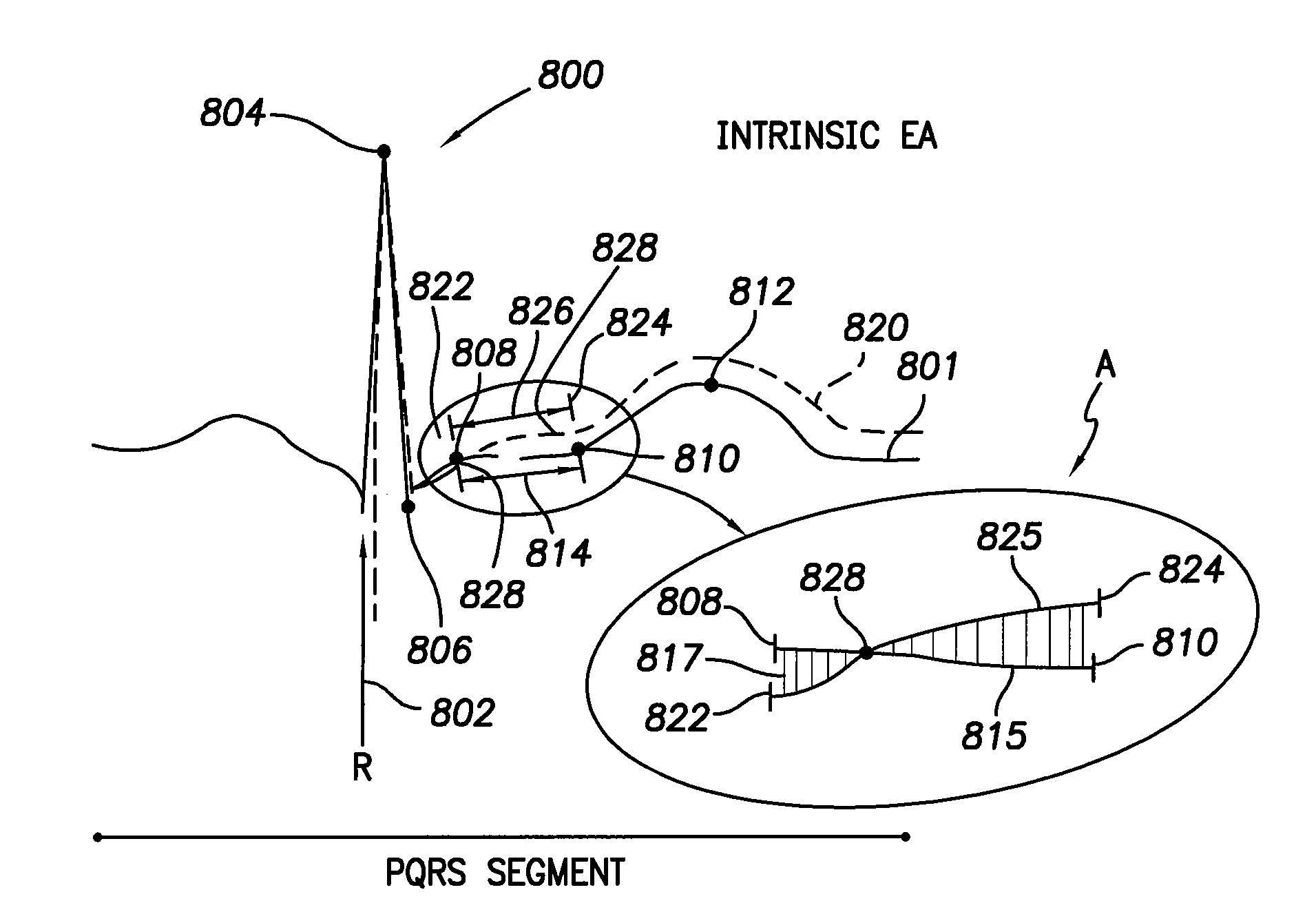
[0007]Optionally, the method may provide locating physiologic state indicators within the baseline trace that define boundaries for the ischemia detection window. The physiologic state indicator may be located by successively comparing adjacent points along the baseline composite trace with one another. Furthermore, the physiologic state indicators represent a second slope change following at least one of an R-wave marker and a V-wave marker. Alternatively, the physiologic state indicator may be located by identifying a derivative of the baseline composite trace. In addition, the method may include determining the fiducial point within the baseline segment by analyzing potential fiducial points and identifying the potential fiducial point that yields a desired relation between the baseline segment and new segment traces. A fiducial point may be located that gives a maximum difference between data values of the baseline segment and an actual segment traces during a ST window.

Problems solved by technology

Elevation or depression of the ST segment in an IEGM may result when there are abnormalities in the polarizations of cardiac tissue during an acute myocardial infraction (MI).
However, not all ST segment shifts are indicative of MI or other injury to the cardiac muscle.
Instead, a ST segment shift above or below the baseline may result because of “axis shifts”, electrical noise, cardiac pacing, high sinus or tachycardia cardiac rates that distort the IEGM waveform.
However, conventional pacemakers or defibrillators do not monitor disease progression by using a running average of cardiac cycles to determine shifts in the ST segment.
Furthermore, typical pacemakers require a user to manually set an isoelectric point, which drifts from patient to patient; thereby preventing any automatic determination of ST shift.
However, conventional approaches to ischemic events have not satisfactorily determined ischemia using ST segment shifts.

Method used


Image

  • Method and system for automatically calibrating ischemia detection parameters
  • Method and system for automatically calibrating ischemia detection parameters
  • Method and system for automatically calibrating ischemia detection parameters

Examples


Embodiment Construction

[0028]In the following detailed description, reference is made to the accompanying drawings which form a part hereof, and in which is shown by way of illustration specific embodiments in which the present invention may be practiced. These embodiments, which are also referred to herein as “examples,” are described in sufficient detail to enable those skilled in the art to practice the invention, and it is to be understood that the embodiments may be combined, or that other embodiments may be utilized and that structural, logical and electrical changes may be made without departing from the scope of the present invention. For example, embodiments may be used with a pacemaker, a cardioverter, a defibrillator, and the like. The following detailed description is, therefore, not to be taken in a limiting sense, and the scope of the present invention is defined by the appended claims and their equivalents. In this document, the terms “a” or “an” are used, as is common in patent documents, ...


PUM


Abstract

A method and system for automatically determining ischemia detection parameters are provided. The method includes obtaining a baseline trace indicative of a cardiac behavior, determining an ischemia detection window based on at least one physiologic state indicator within the baseline trace, and automatically identifying a fiducial point based on the baseline segment trace. The baseline trace includes a baseline segment within the ischemia detection window; where the ischemia detection window and the fiducial point may constitute ischemia detection parameters.

Description

BACKGROUND OF THE INVENTION[0001]Embodiments of the present invention pertain generally to implantable medical devices, and more particularly pertain to implantable medical devices that automatically calibrate ischemia detection parameters.[0002]Many patients at risk of cardiac ischemia have pacemakers, ICDs or other medical devices implanted therein. Electrocardiograms (ECG) are useful for diagnosing ischemia and locating damaged areas within the heart. Cardiac ischemia is a condition whereby heart tissue does not receive adequate amounts of oxygen and is usually caused by a blockage of an artery leading to heart tissue. ECGs are composed of various waves and segments that represent the heart depolarizing and repolarizing. ST segment represents the portion of the cardiac signal between ventricular depolarization and ventricular repolarization. While P-waves, R-waves and T-waves may be generally considered features of a surface electrocardiogram (ECG), for convenience and generality...

Claims


Application Information

Patent Timeline
Patent Type & Authority Patents(United States)
IPC IPC(8): A61N1/362
CPCA61B5/0452A61B5/7203A61N1/3702A61N1/37247G06F19/3406G06F19/3412A61B5/349G16H40/40G16H40/63
Inventor KRISHNASWAMY, HARISHKENI, ANIL
Owner PACESETTER INC
Why Eureka
Try Eureka