Dunnage production and packaging

a technology of cushioning and production, applied in the direction of packaging goods, paper/cardboard containers, paper/cardboard articles, etc., can solve the problems of not always getting a good seal, premature dropping of the pick and place device, and not always getting a pad picked up

Inactive Publication Date: 2011-01-11
RANPAK CORP
View PDF37 Cites 18 Cited by
  • Summary
  • Abstract
  • Description
  • Claims
  • Application Information

AI Technical Summary

Benefits of technology

[0011]The present invention provides a pad production and packaging system and method for automatically producing dunnage pads and inserting one or more of the produced dunnage pads into a container for packaging of an article in the container. The invention is characterized by a pad discharge assembly and / or pad insertion assembly, and preferably both integrated together to provide an automatic pad production and packaging system and method that afford advantages over existing pad production and packaging arrangements.
[0018]The invention also provides a sensor curtain for use with a discharge assembly that has at least one side thereof only partially blocked when a pad is being fed into the discharge assembly, the partially blocked side of the discharge assembly allowing possible insertion of a foreign object into the discharge assembly through the partially blocked side thereof and into contact with a severing device located adjacent an entry end of the discharge assembly. The sensor curtain is disposed to detect the insertion of a foreign object through the partially blocked side of the discharge assembly and provide an output for disabling a severing operation. In this manner, damage to the foreign object and / or severing assembly may be prevented. The sensor curtain may be configured to detect different sizes of foreign objects by varying a grid size of the sensor curtain. Moreover, the sensor curtain may be disposed to determine when the aforesaid gating device has returned to a pad receive condition, as by determining when a gate or gates of such gating device have returned to their closed position for receiving a pad and thus are no longer in their open position for discharging a pad.

Problems solved by technology

Although such devices have been successfully used in the past, a problem arises when highly crumpled surfaces are presented to the suction elements in that a good seal can not always be obtained.
This may result in a pad not getting picked up or the pad prematurely dropping off of the pick and place device.

Method used


Image

  • Dunnage production and packaging
  • Dunnage production and packaging
  • Dunnage production and packaging

Examples


Embodiment Construction

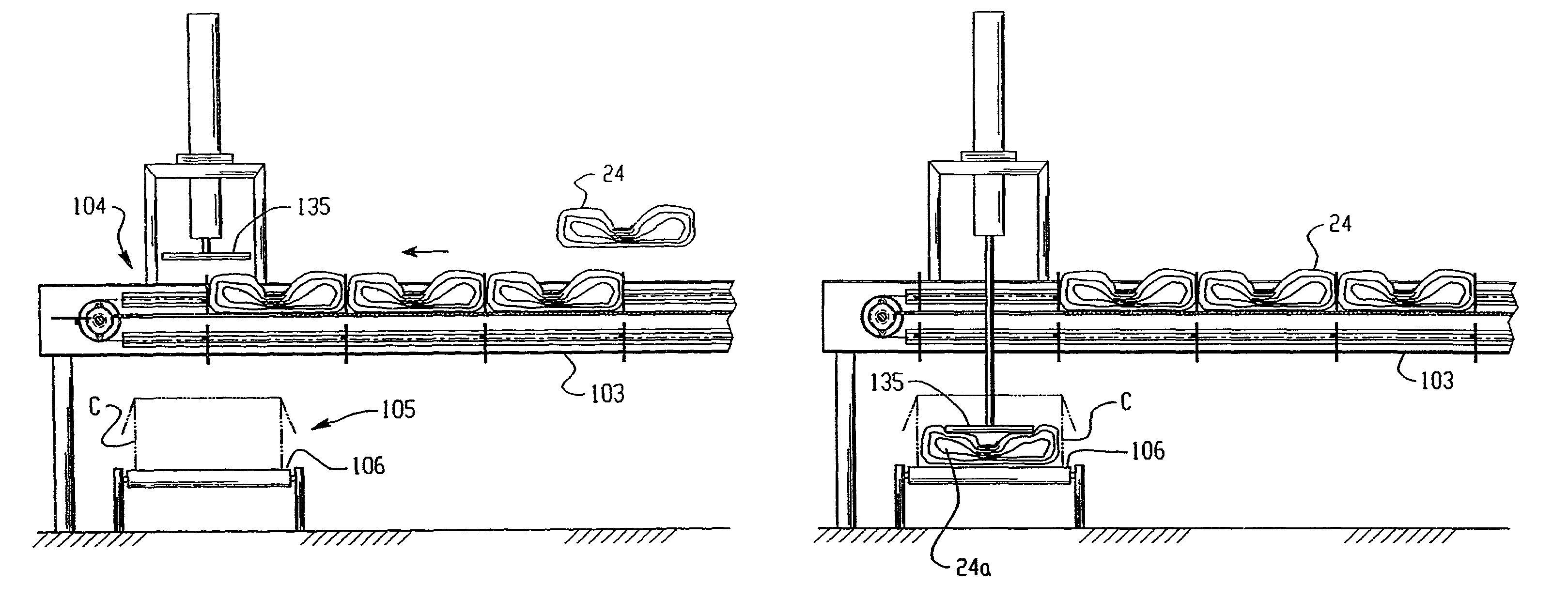
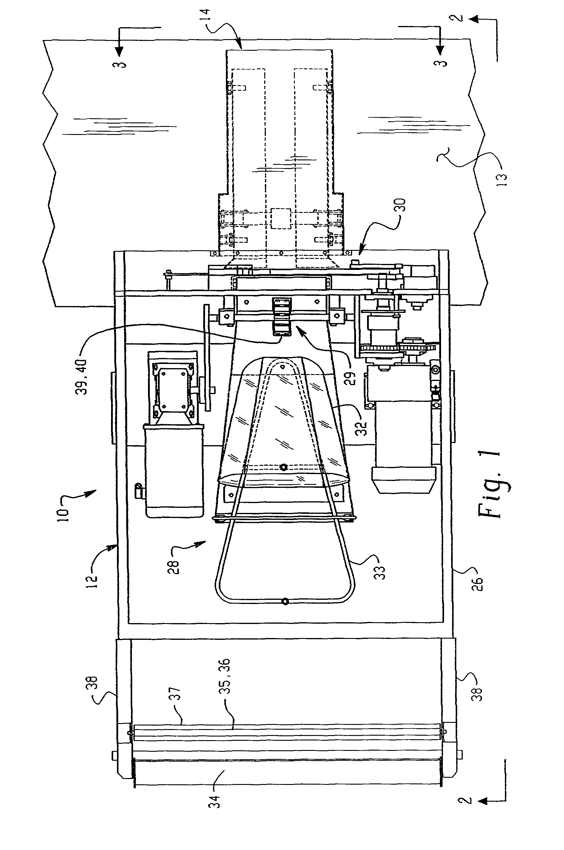
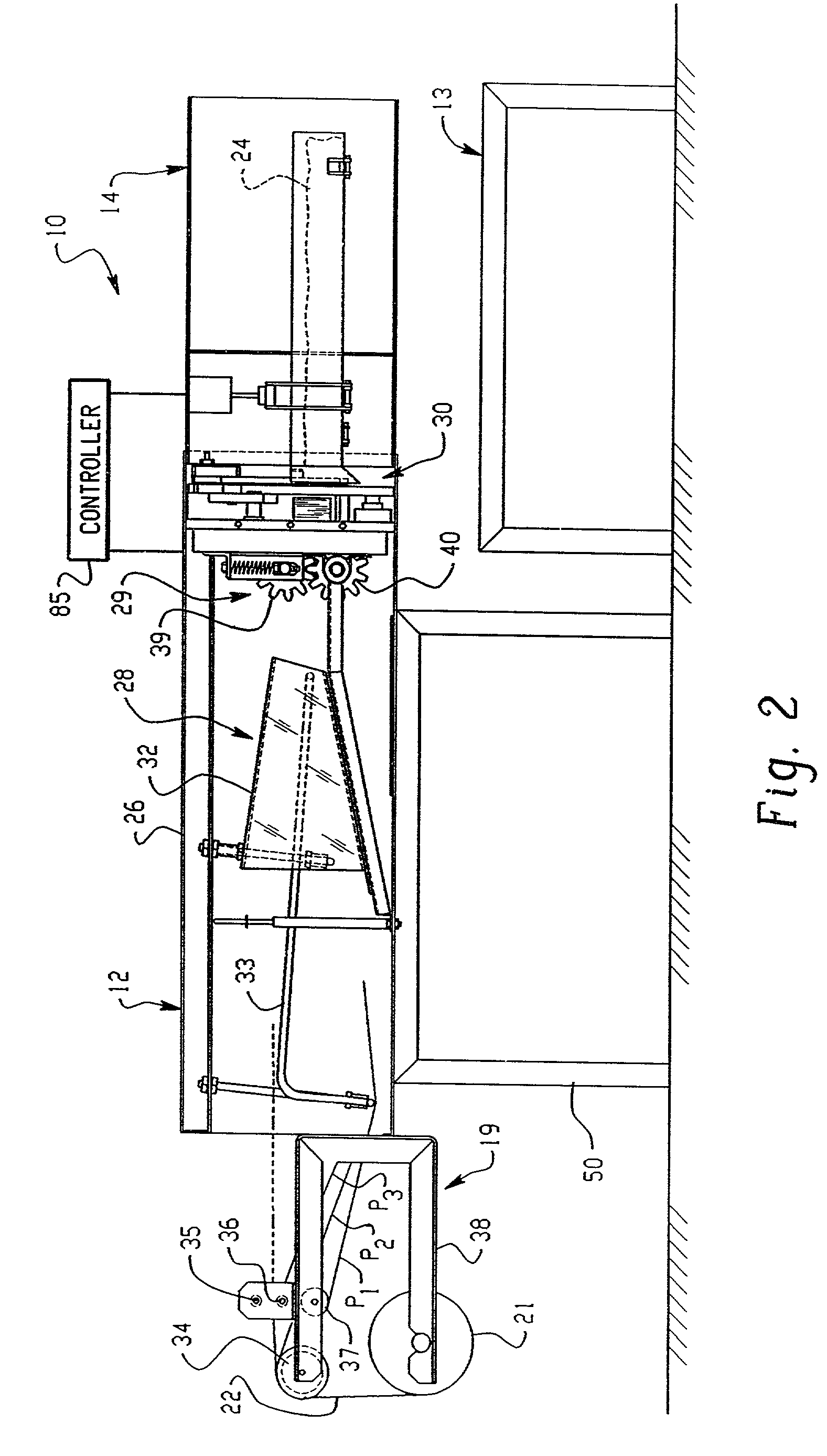
[0050]Referring now to the drawings in detail and initially to FIGS. 1-3, a preferred embodiment of a pad production and delivery system 10 according to the present invention is shown. The system 10 generally comprises a cushioning conversion machine 12 for producing dunnage pads, a conveyor 13 for transporting the pads away from the machine 12, and a pad discharge gate 14 for receiving the pads from the conversion machine and transferring them to the conveyor.

[0051]As shown in FIGS. 1 and 2, the conversion machine 12 has a stock supply which, in the illustrated embodiment, includes an integral stock roll holder assembly 19 for supporting a roll 21 of sheet stock material 22. The stock material 22 preferably consists of one or more, typically two or three, superimposed plies P1, P2 and P3 (FIG. 2) of biodegradable, recyclable and reusable sheet material, such as Kraft paper rolled onto a hollow cylindrical tube. The machine 12 converts this stock material 22 into a crumpled strip of...


PUM

PropertyMeasurementUnit
widthaaaaaaaaaa
widthaaaaaaaaaa
distanceaaaaaaaaaa

Abstract

A packaging system for automatically producing dunnage pads and inserting one or more of the pads into a container for packaging an article in the container. The invention includes a pad discharge assembly and / or pad insertion assembly. The discharge assembly includes a gating device for effecting passage of the pad out of a holding zone in a direction transverse to the pad length and onto a working surface, preferably a conveyor. The conveyor conveys the pad into a pad insertion zone in a first direction, and a pusher assembly is operative to push the pad from the pad insertion zone in a direction transverse to the first direction. A plunger is provided for pushing a pad located at the pad insertion zone through an opening over which the pad is conveyed for insertion into a container.

Description

RELATED APPLICATION DATA[0001]This application is a divisional of Ser. No. 09 / 156,109, filed Sep. 18, 1998, now U.S. Pat. No. 6,421,985 which claims priority under 35 U.S.C. 119(e) of Ser. No. 60 / 099,236, filed Sep. 4, 1998, Ser. No. 60 / 086,010, filed May 19, 1998, and Ser. No. 60 / 059,290, filed Sep. 18, 1997, all of which are incorporated herein by reference in their entirety.FIELD OF THE INVENTION[0002]The invention herein described relates generally to the art of cushioning conversion machines (dunnage converters) that produce pads useful as dunnage for packing articles for shipment, storage or otherwise. More particularly, the invention relates to systems employing one or more of such machines and mechanisms for handling the pads produced by such machine or machines for controlled transport and / or delivery of the pads in a useful manner, including in particular the insertion of the pads into containers for packing an article in the container.BACKGROUND OF THE INVENTION[0003]Cush...

Claims


Application Information

Patent Timeline
Patent Type & Authority Patents(United States)
IPC IPC(8): B65B23/00B26D7/32B32B1/00B31D5/00B65B5/10
CPCB31D5/0047B31D2205/0023B31D2205/0047B31D2205/0058B31D2205/0064B31D2205/007B31D2205/0082B31D2205/0088Y10S493/967B32B1/00
Inventor SIMMONS, JR., JAMES A.RATZEL, RICHARD O.HARDING, JOSEPH J.
Owner RANPAK CORP
Why Eureka
Try Eureka