Mud pump receiving flange and plug retainer

a technology of plug retainer and receiving flange, which is applied in the direction of machines/engines, liquid fuel engines, positive displacement liquid engines, etc., can solve the problems of difficult and time-consuming, corrosive and abrasive drilling fluid used in wells, and screwing the plug retainer from the receiving flange is difficult and time-consuming, so as to achieve rapid engagement and disengagement

Inactive Publication Date: 2011-01-11
WALTERS JIMMY A
View PDF16 Cites 40 Cited by
  • Summary
  • Abstract
  • Description
  • Claims
  • Application Information

AI Technical Summary

Benefits of technology

[0005]The present invention presents a plug retainer and receiving flange that has a unique arrangement of coupling threads that will provide a rapid engagement and disengagement of the plug retainer from the receiving flange in order to provide ready access to the valve systems. The arrangement of the coupling threads on the plug retainer and the receiving flange into a plurality of corresponding blank segments and threaded segments allows for the engagement and disengagement of the plug retainer from the receiving flange with only a partial turn of the plug retainer on the receiving flange.
[0006]It is that that the unique arrangement of engagement threading on the plug retainer and the receiving flange will require only one-sixth rotation of the plug retainer on the receiving flange, without force, to provide sufficient sealing of the plug retainer with the receiving flange even under the high pressure and flow rates typically seen with drilling fluids. Further, the one-sixth required rotation will provide ease of disengagement of the plug retainer from the receiving flange when access to valve components is necessary.

Problems solved by technology

The drilling fluids used in wells are often corrosive and abrasive in nature.
Often it is difficult and time consuming to unscrew and screw the plug retainer from the receiving flange, when the plug retainer is removed and replaced for maintenance on the valve section of the pump is necessary.

Method used


Image

  • Mud pump receiving flange and plug retainer
  • Mud pump receiving flange and plug retainer
  • Mud pump receiving flange and plug retainer

Examples


Embodiment Construction

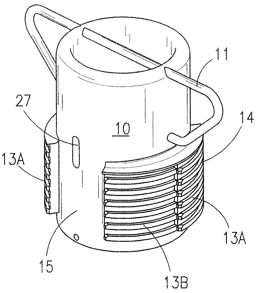
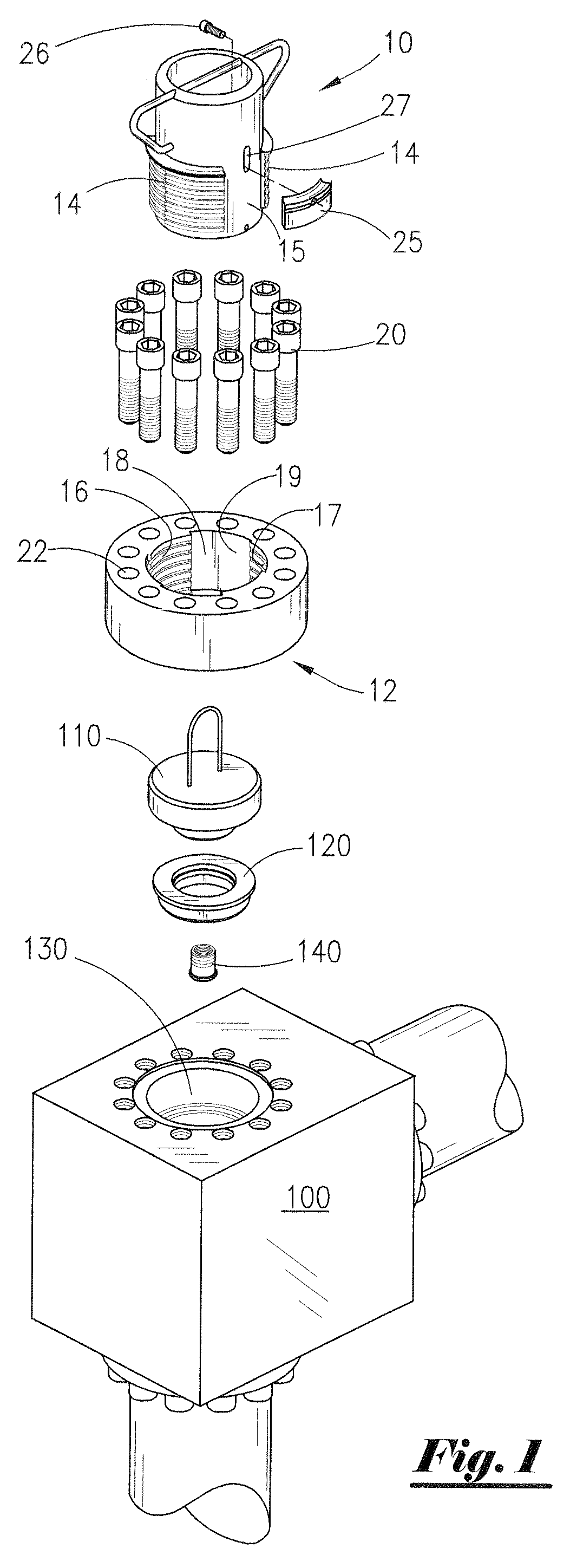
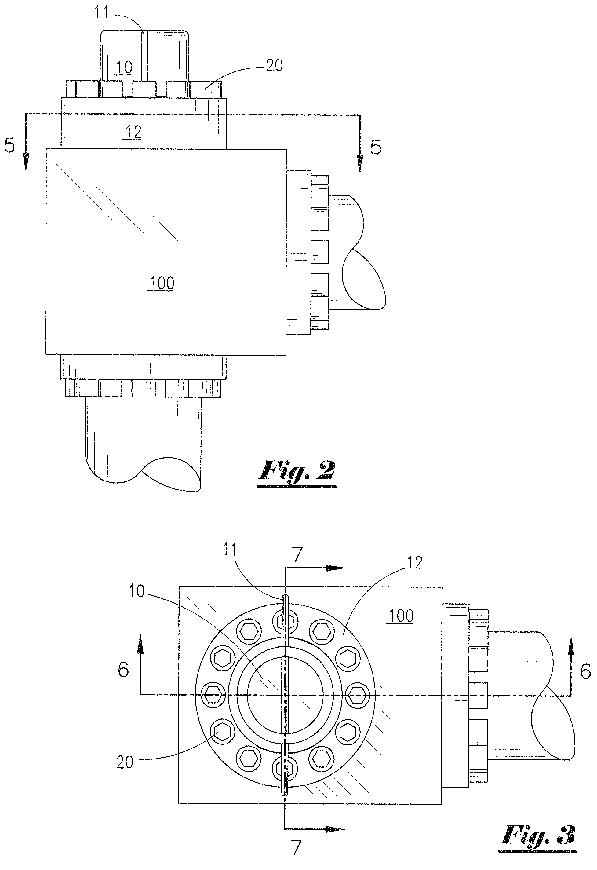
[0028]FIG. 1 is an exploded view of a plug retainer 10, a receiving flange 12, a seal plug 110, and a module pot plug seal 120 of the present invention for assembly with the valve guide bushing components 140 on the fluid module 100 of a mud pump.

[0029]The plug retainer 10 has on its periphery at least two lines of axially disposed thread segments 14, each line of thread segments 14 having a plurality of threads 13. The lines of thread segments 14 are spaced apart from each other a desired amount to form gaps 15 between the thread segments 14.

[0030]Similarly, the receiving flange 12 has bore 18 to correspond with the plug retainer 10. Along the bore 18 of the receiving flange 12 are at least two lines of axially disposed thread segments 16, each line of thread segments 16 having a plurality of threads 17. The lines of thread segments 16 are spaced apart from each other a desired amount to form gaps 19 between the lines of thread segments 16.

[0031]Each line of thread segments 14 on t...


PUM


Abstract

A plug retainer and receiving flange for a mud pump fluid module pipe comprising a plug retainer and a receiving flange. The threads of the plug retainer are configured into at least two segments that are axially disposed opposite each other upon the periphery of the plug retainer. Each segment of plug retainer threads has at least two columns of threads that are progressively stepped outward from said the periphery of said plug retainer. The receiving flange has at least two segments of flange threads axially disposed upon the periphery of the flange bore that are disposed opposite each other on the flange bore to form gaps between each of the thread segments, each segment of receiving flange threads has at least two columns of threads that are progressively stepped inward and are configured to correspond with the plug retainer thread segments. A means to rotate the plug retainer within the bore of the receiving flange is provided to engage the plug retainer threads with the receiving flange threads. The plug retainer threads and the receiving flange threads may be horizontally disposed and a lock plate may be provided to avoid inadvertent turning of the plug retainer in the receiving flange.

Description

[0001]This application claims priority to U.S. Provisional Application Ser. No. 61 / 019,484 filed Jan. 7, 2008 by Jimmy A. Walters, the entire contents of which is hereby incorporated by reference.FIELD OF INVENTION[0002]The invention herein disclosed relates to components for high pressure fluid pumps such as those typically used to pump drilling fluid (“mud”) that is used in the drilling of wells and in particular relates to a receiving flange and plug retainer for components for high pressure drilling mud pumps for deep wells common to the oil and gas industry.BACKGROUND OF INVENTION[0003]Drilling fluids are pumped into a well by mud pumps through a series of mud lines and valves. Typically, these pumps introduce the drilling fluids into a pipe under high pressure and with a high velocity. The drilling fluids used in wells are often corrosive and abrasive in nature. Use of such fluids under such conditions and with such physical properties typically requires the frequent maintenan...

Claims


Application Information

Patent Timeline
Patent Type & Authority Patents(United States)
IPC IPC(8): F16L55/10
CPCE21B21/01F04B15/02F04B53/16F16L55/1125
Inventor WALTERS, JIMMY A.
Owner WALTERS JIMMY A
Why Eureka
Try Eureka