Device for controlling a vortex trail generated by the oblong element of an aircraft bearing surface

Inactive Publication Date: 2011-01-11
AIRBUS OPERATIONS SAS
View PDF10 Cites 13 Cited by
  • Summary
  • Abstract
  • Description
  • Claims
  • Application Information

AI Technical Summary

Benefits of technology

[0019]since the control means has a rounded edge between the two flanks, said control means can be bypassed by the local fluid flow in the cruising phase of the flight, that is to say at local angles of incidence at the control means which are small and range, for example, between −5° and +5°, thus avoiding any boundary layer separation in such flight situations.
[0020]As a result, the control means according to the invention generates an additional vortex of viscous origin when positioned at a steep angle of incidence with respect to its main axis, that is to say when the wing structure of the aircraft is close to stalling conditions. In the context of the present invention, a viscous vortex should be understood to mean a vortex spinning off from a singular point of zero parietal friction at the wall, the initial axis of which is perpendicular to the wall. This addit

Problems solved by technology

Now, since the distance between this control means and said vortex trail is relatively great, it is difficult to find an appropriate position for said control means on the nacelle in order to lead the additional vortex precisely to the vortex trail.
Because of the latter characteristic, a conventional control means does, nonethe

Method used


Image

  • Device for controlling a vortex trail generated by the oblong element of an aircraft bearing surface
  • Device for controlling a vortex trail generated by the oblong element of an aircraft bearing surface
  • Device for controlling a vortex trail generated by the oblong element of an aircraft bearing surface

Examples


Embodiment Construction

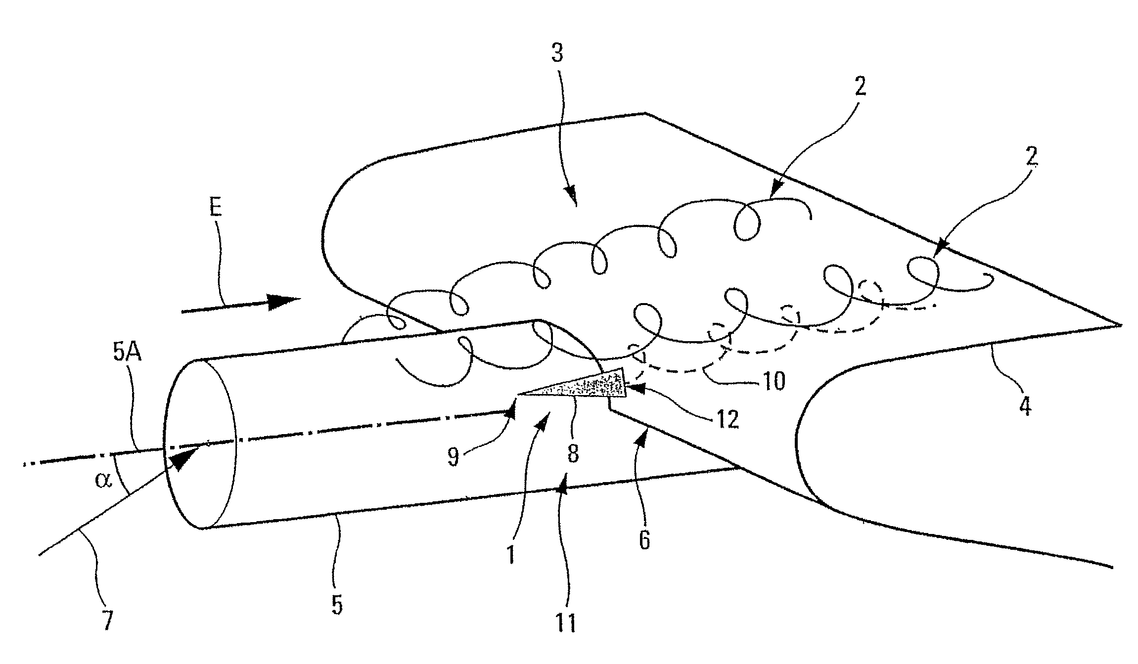
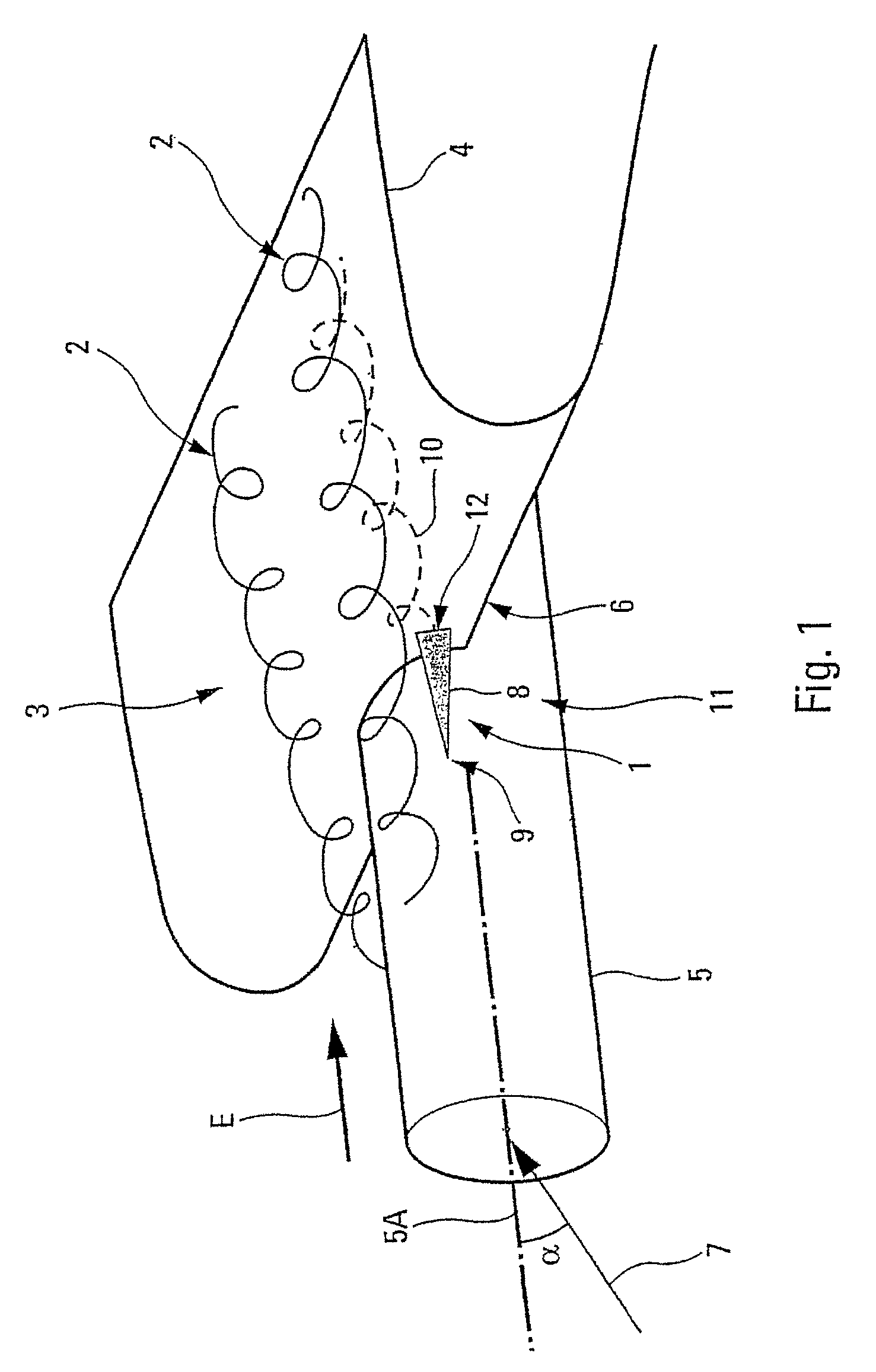
[0033]The device 1 according to the invention and depicted schematically in FIG. 1 is intended to control a vortex trail 2 that there is on the suction-face side 3 of a lift-generating surface 4 of an aircraft (not depicted), particularly on the suction-face side of an airplane wing. This vortex trail 2 is generated in the usual way (essentially at steep angles of incidence) by an oblong element 5 mounted under this lift-generating surface 4, and protruding in the upstream direction (in the direction E of the local fluid flow) at least partially beyond the leading edge 6 of said lift-generating surface 4. Said oblong element 5 may in particular be a jet engine, an in-flight refuelling pod or a payload such as a missile for example.

[0034]More specifically, it is an object of the device 1 according to the invention to control the vortex trail 2 for a position of the aircraft close to stalling conditions, that is to say for a local angle of incidence α (which is defined between the lon...


PUM


Abstract

A device for controlling a vortex trail generated by an oblong element of an aircraft bearing surface includes a control component arranged on a fixing element of the oblong element and on a bearing surface such that a base of the control component contacts the leading edge of the bearing surface. The control component has a triangular shape, on a plane perpendicular to the longitudinal axis thereof, whose two adjacent sides form flanks interconnected by a rounded edge.

Description

FIELD OF THE INVENTION[0001]The present invention relates to a device for controlling at least one vortex trail generated on the suction-face side of a lift-generating surface of an aircraft, said vortex trail being generated by at least one oblong element which is mounted under this lift-generating surface.[0002]More specifically, although not exclusively, the present invention applies to the control of fluid flows over the suction-face side of the wings of an airplane, which are equipped with oblong elements such as jet engines, in-flight refuelling pods or payloads, for example missiles. The objective is, more specifically, that of controlling the vortex trail at an airplane position close to stalling conditions so as to improve the maximum lift that the airplane wing structure can produce in the presence of one or more oblong elements such as those mentioned above.BACKGROUND OF THE RELATED ART[0003]Documents U.S. Pat. Nos. 3,744,745 and 4,685,643 disclose wake-control devices wh...

Claims


Application Information

Patent Timeline
IPC IPC(8): B64C23/06
CPCB64C7/02B64C23/06Y02T50/162Y02T50/10
Inventor ATINAULT, OLIVIER
Owner AIRBUS OPERATIONS SAS
Why Eureka
Try Eureka