Hydraulically positioned shaft bearing attachment system and method

a technology of hydraulic positioning and shaft bearings, applied in the direction of bearings, roller bearings, shafts, etc., can solve the problems of reducing the service life of the bearing, so as to reduce the frictional loss in the drive mechanism. , accurately determine the final position, and the effect of constant load

Active Publication Date: 2011-01-11
DODGE INDS +1
View PDF8 Cites 18 Cited by
  • Summary
  • Abstract
  • Description
  • Claims
  • Application Information

AI Technical Summary

Benefits of technology

[0010]The present invention offers a novel approach that addresses some or all of the issues and problems discussed above. In one implementation, the invention may generally include an internal flange, an external flange, a tapered sleeve, a piston, and a plurality of fasteners. The system mounts a bearing assembly to a shaft by driving the tapered sleeve into the assembly via an innovative hydraulic positioning system. The system is incorporated into the parts and eliminates the need for custom fixturing or special tooling. Unlike other mounting systems that make use of a single large diameter drive thread, the present invention uses a hydraulically loaded piston to engage the sleeve between the bearing assembly and the shaft. This loading system effectively reduces the frictional loses in the drive mechanism and does not require the user to overcome an excessive amount of drive thread resistance. This also has the very important benefit of allowing the user to accurately determine and reliable quantify an initial position of the sleeve as it is driven into engagement by monitoring the pressure applied to the piston.
[0011]Once the initial position is determined, a linear indicator may be used to measure the movement of the sleeve and / or the bearing assembly relative to the initial position. The user can accurately determine the final position given a known pre-determined distance between the initial position and the final position. Furthermore, the user may secure the sleeve in place by threading a screw into the external flange thereby abutting the piston to maintain a constant load on the sleeve. Finally, the system is configured to remain in place after the bearing is mounted to the shaft making it readily available should the bearing require maintenance.
[0012]The system further includes a removal chamber that facilitates extraction of the sleeve from between the bearing and shaft using a pressure loaded hydraulic fluid. The removal chamber is formed between the interface of the bearing assembly and a tapered outside diameter of the sleeve. As mentioned above, because the attachment system remains in place, very little additionally tooling is required to service the bearing.

Problems solved by technology

Those skilled in the art are familiar with the operation of this type of system and the limitations of using such systems.
A first limitation relates to part tolerance and the initial clearance between these parts (i.e., the shaft outside diameter, the sleeve width, the inside diameter of the bearing assembly, etc.).
This initial position can be problematical in that, if not accurately established, it can lead to further assembly problems as discussed below.
No current bearing mounting system provides an easy, reliable, and consistent method to determine this initial position.
Too much, and particularly too little internal clearance, such as resulting from overloading the internal ring, can result in damage to the bearing and eventual mechanical system failure.
Tapered sleeve arrangements can overload bearings, effectively reducing the internal clearance by expanding the inner ring of the bearing.
In current bearing mounting systems, it may be difficult to determine exactly how much inner ring expansion might occur during the assembly process.
Another limitation of tapered sleeve mounting systems relates to the manner in which the tapered sleeve is driven or drawn into engagement between the bearing assembly and the shaft.
Consequently, special tooling is often required to torque the larger components that engage the oversized threads.
Furthermore, this tooling does not solve the problem of accurately determining the initial position.
A further issue with existing bearing mounting systems is that large diameter threads have larger contacting areas and thus frictional losses are increased.
This is, of course, particularly problematic for large shaft and bearing sizes.
These forces, when combined with the frictional forces of the tapered system itself, result in very large moments that must be imparted on the components to thread the sleeve properly into engagement.
Also, those skilled in the art will appreciate that the frictional force in this thread can vary greatly resulting in a great deal of uncertainty in the torque required to engage the sleeve in place.
This is problematic because this torque value is often used to determine the initial position and / or the fully engaged position.
If this torque is not consistent, the proper positioning of the sleeve will be uncertain.
Another limitation of tapered sleeve mounting systems relates to the force required to extract the sleeve from between the bearing assembly and the shaft.
In large diameter bearing systems (e.g., 10 inches and larger), this contact stress can be very high, requiring a great deal of force to disengage the sleeve from the bearing assembly.
Some mounting systems require the user to overcome this force manually, making it extremely difficult for the user to disengage the bearing from the shaft.

Method used


Image

  • Hydraulically positioned shaft bearing attachment system and method
  • Hydraulically positioned shaft bearing attachment system and method
  • Hydraulically positioned shaft bearing attachment system and method

Examples


Embodiment Construction

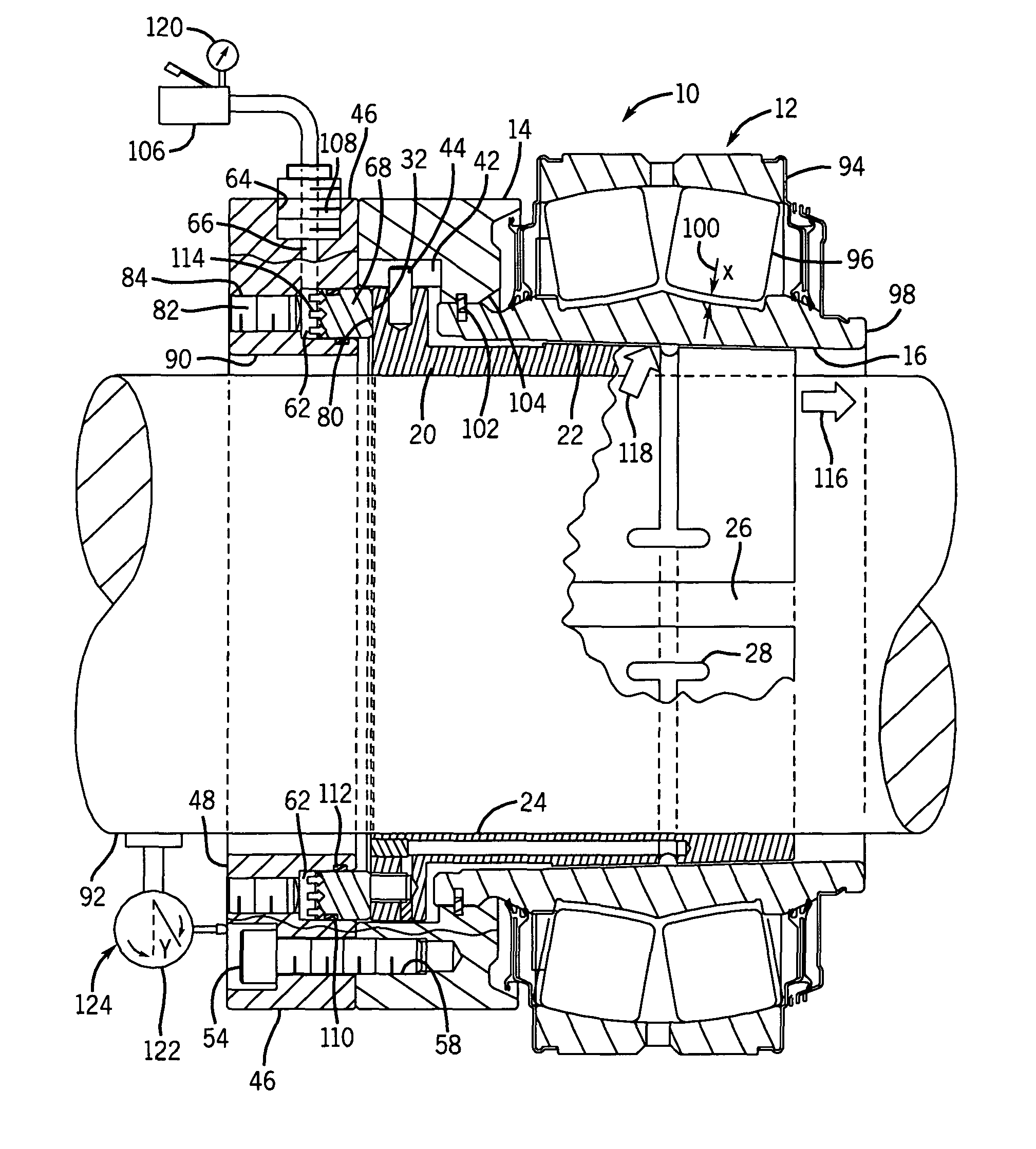
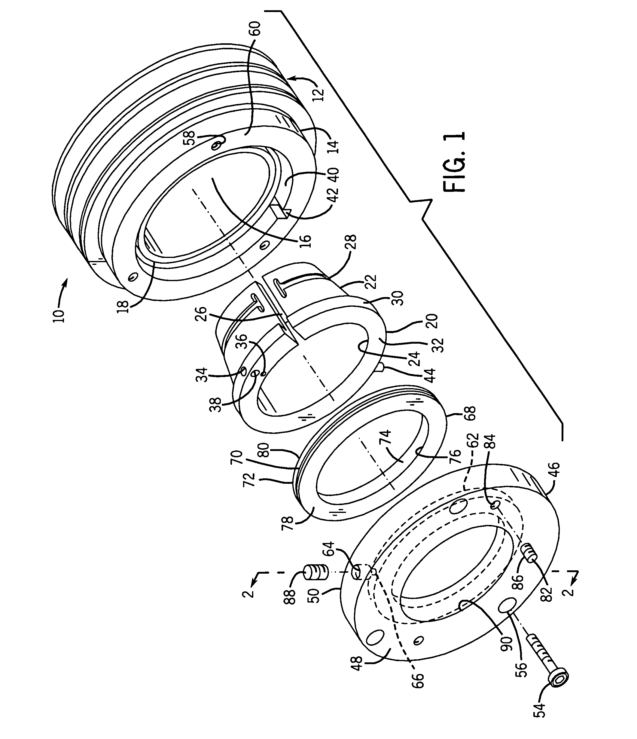
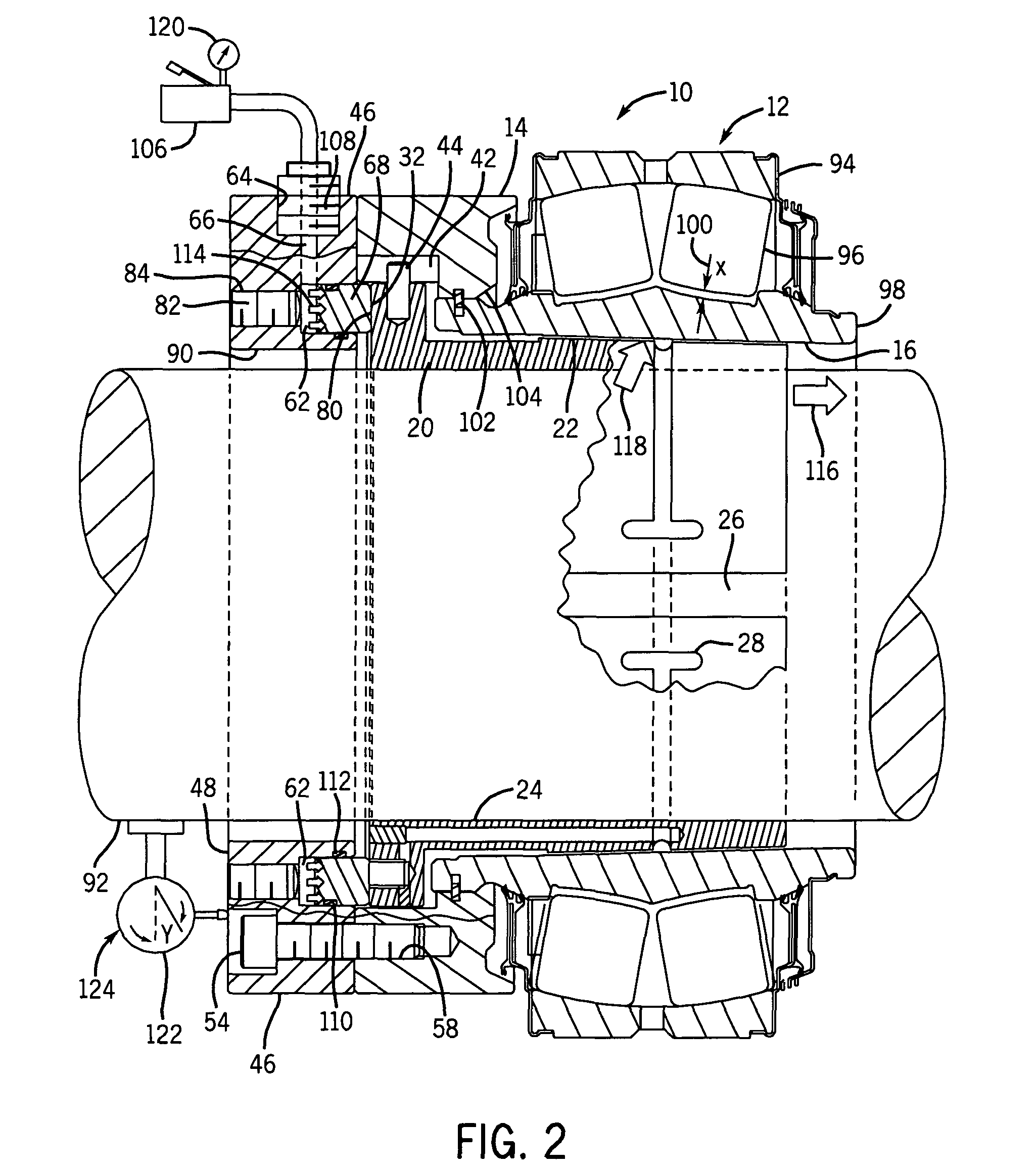
[0018]Turning now to the drawings, FIG. 1 illustrates the elements of the hydraulically positioned bearing attachment system in accordance with an exemplary embodiment of the invention. The system includes a bearing kit 10 comprising of a bearing assembly 12 and an internal flange 14. The bearing assembly 12 has a tapered inside diameter 16 and a guide diameter 18 to radially locate and mate with an internal diameter of the internal flange 14. A sleeve 20 having a tapered outside diameter 22 engages the tapered inside diameter 16 of the bearing assembly 12. The sleeve 20 has a uniform inside diameter 24 and an axial split 26 allowing it to clamp down on a circular shaft when the outside diameter 22 is engaged. It should be noted that the present system may be employed with components that are differently configured, particularly insomuch as the engaging tapers are concerned. For example, to avoid tapering the inside of the bearing assembly itself, another sleeve may be interposed in...


PUM

PropertyMeasurementUnit
diametersaaaaaaaaaa
diameteraaaaaaaaaa
pressureaaaaaaaaaa

Abstract

A mounting system is disclosed for mounting a bearing assembly or other mechanical element to a shaft. The mounting system uses a tapered sleeve mechanism to secure the bearing assembly on the shaft. Specifically, a pressure loaded piston drives the sleeve from a pre-assembled position to an initial position. The initial position is determined by monitoring the pressure applied to the piston. Once the initial position has been reached, a linear indicator is used to measure the axial sleeve movement from the initial position to a final position. The system remains in place after the bearing is installed on the shaft and facilitates removal of the bearing assembly from the shaft.

Description

BACKGROUND[0001]The present invention relates to the field of rotating machinery and to systems for mechanically mounting an element to a shaft. More specifically, the invention relates to an innovative hydraulically positioned shaft bearing attachment system used to mount a bearing assembly to a shaft.[0002]Rotary mechanical systems include elements, such as bearings, that allow relative rotational movement between respective parts. For example, a rotary system might include a stationary housing that supports a rotating shaft via a bearing assembly. The bearing assembly is typically mounted directly to the shaft and allows for the relative rotational movement between the stationary housing and the rotating shaft.[0003]A variety of mounting systems are known and commercially available for mounting a bearing assembly or other mechanical element to a shaft. Some of these systems make use of a tapered sleeve that fits snuggly between the outer periphery of the shaft and the inner ring ...

Claims


Application Information

Patent Timeline
Patent Type & Authority Patents(United States)
IPC IPC(8): F16C35/078
CPCF16C35/073F16C35/078Y10T403/7005Y10T29/497Y10T403/7007Y10T29/5383Y10T29/49771Y10T29/49696Y10T29/49826Y10T29/4978Y10T29/49698F16C23/086F16C2226/16F16C19/38
Inventor HEWITT, WILLIAM G.
Owner DODGE INDS
Why Eureka
Try Eureka