

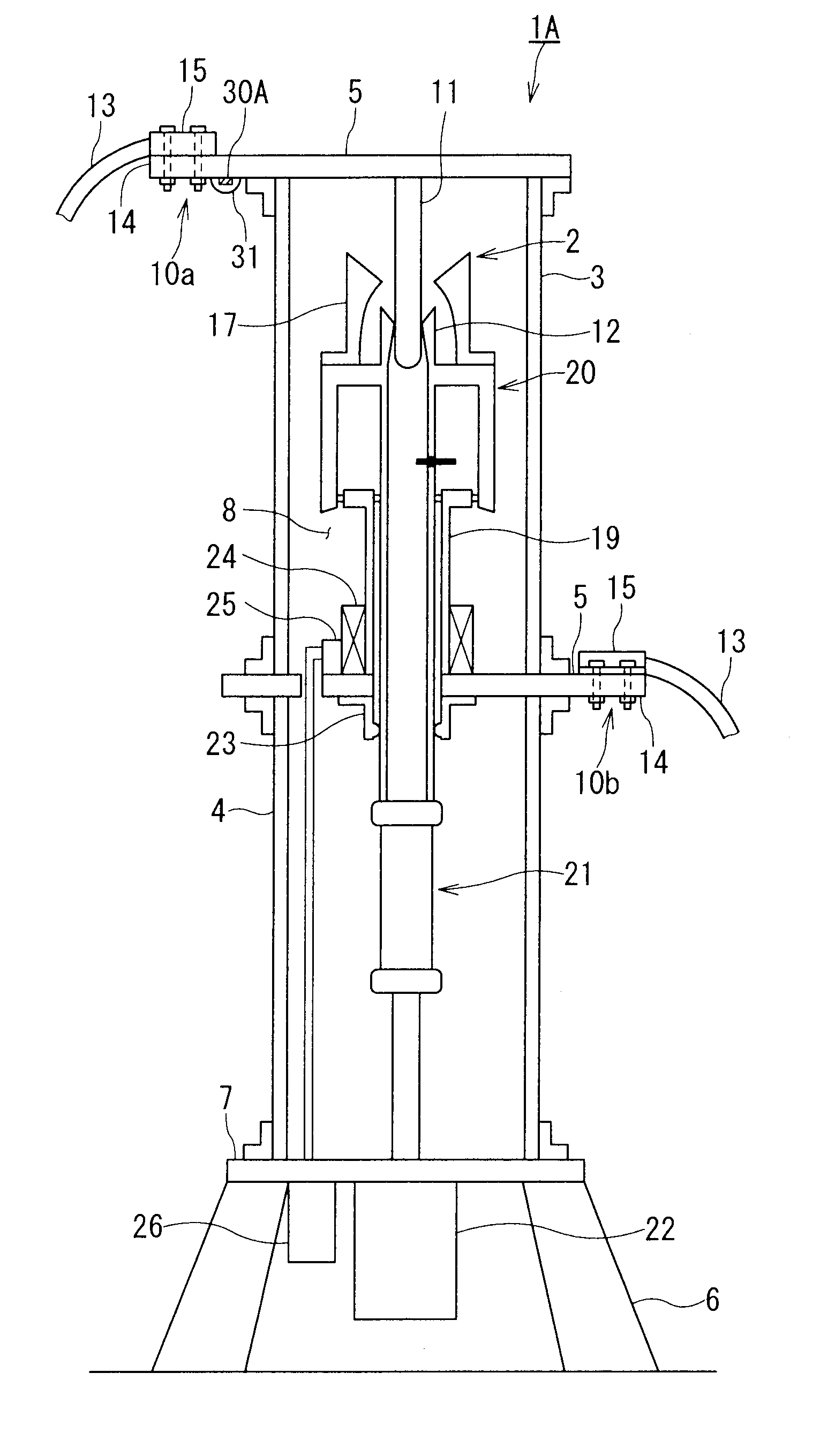
Sensor attached IC tag application high voltage equipment
a technology of high-voltage equipment and ic tags, which is applied in the direction of casings/cabinets/drawers, instruments, casings/cabinets/drawers, etc., can solve the problems of loss of electric power transmission, degradation of insulating materials of equipment, and extremely large number of measurement points, so as to shorten the inspection period. , the effect of shortening the inspection period
- Summary
- Abstract
- Description
- Claims
- Application Information
AI Technical Summary
Benefits of technology
Problems solved by technology
Method used
Image

Examples
second embodiment
[0061]FIG. 4 is a vertical cross-sectional view of a temperature sensor attached IC tag application insulator gas circuit breaker 1B according to another example (second embodiment) of the present invention.
[0062]In the temperature sensor attached IC tag application insulator gas circuit breaker 1B illustrated in FIG. 4, a mounting hole 55 formed into a groove shape for mounting the temperature sensor attached IC tag 30A is provided to the electrode unit 10a. Then, the temperature sensor attached IC tag 30A is detachably mounted to the mounting hole 55. Further, as illustrated in FIG. 4, in the temperature sensor attached IC tag application insulator gas circuit breaker 1B, the electrostatic shielding member 31 is not mounted, and the temperature sensor attached IC tag 30A does not have the electrostatic shield by the electrostatic shielding member 31.
[0063]According to the temperature sensor attached IC tag application insulator gas circuit breaker 1B, even when a high voltage is a...
third embodiment
[0065]FIG. 5 is a vertical cross-sectional view of a temperature sensor attached IC tag application insulator gas circuit breaker 1C according to another example (third embodiment) of the present invention.
[0066]As illustrated in FIG. 5, in the temperature sensor attached IC tag application insulator gas circuit breaker 1C, the mounting hole 55 of the temperature sensor attached IC tag application insulator gas circuit breaker 1B is provided to the lower electrode unit 10b as well. Further, the temperature sensor attached IC tag application insulator gas circuit breaker 1C is constructed in such a manner that the electrostatic shielding member 31 is mounted in the vicinity of the entrance of the mounting hole 55 so that the temperature sensor attached IC tag 30A is covered and the mounting hole 55 is clogged.
[0067]According to the temperature sensor attached IC tag application insulator gas circuit breaker 1C, the temperature sensor attached IC tag 30A is physically covered by the e...
fourth embodiment
[0068]FIG. 6 is a vertical cross-sectional view of a temperature sensor attached IC tag application insulator gas circuit breaker 1D according to another example (fourth embodiment) of the present invention.
[0069]In comparison to the temperature sensor attached IC tag application insulator gas circuit breaker 1A illustrated in FIG. 1, the temperature sensor attached IC tag application insulator gas circuit breaker 1D is constructed in such a manner that instead of using the electrostatic shielding member 31, the temperature sensor attached IC tag 30A is covered with an electrostatic shielding member 58 processed into a special shape for the electrostatic shielding.
[0070]The electrostatic shielding member 58 is made of a metal and constructed so that, as illustrated in FIG. 6, its distal end is processed to be rounded. Further, the electrostatic shielding member 58 is mounted to the upper electrode unit 10a with a clearance with respect to the upper electrode unit 10a.
[0071]Accordin...
PUM
 Abstract
Description
Claims
Application Information