
Flex circuit lightning protection applique system for skin fasteners in composite structures

a composite structure and lightning protection technology, applied in the installation of lighting conductors, connection to earth, aircraft static dischargers, etc., can solve the problems of unprotected cfrp components, temperature drives the damage level, and composite materials that are state of the art more resistant than aluminum

Active Publication Date: 2011-01-11
THE BOEING CO
View PDF16 Cites 30 Cited by
  • Summary
  • Abstract
  • Description
  • Claims
  • Application Information

AI Technical Summary

Benefits of technology

The present invention provides a lightning protection appliqué that can be attached to a composite surface. The appliqué has multiple layers of conductive material that help to divert electrical energy from a lightning strike. There is also a layer of dielectric material that covers metal surfaces on the composite surface. The appliqué can also have additional components like heater elements for deicing, antenna / sensor elements, or health monitoring circuitry. Overall, this invention helps to protect composite surfaces from lightning strikes and other weather-related damage.

Problems solved by technology

Unfortunately, typical state of the art composites, such as Carbon Fiber Reinforced Plastic (CFRP), are approximately 2000 times more resistive than aluminum.
Typically, temperature drives the damage level created by a lightning strike.
A lightning strike that may have little or no effect on an aluminum structure may damage unprotected CFRP components.
Furthermore, skin fasteners at an exposed surface are most vulnerable to a direct strike and such a strike is most likely to cause sparking at structural joints.
Unfortunately, typical approaches to minimizing the possibility ignition and reducing damage are complicated and difficult to implement in CFRP.
However, this approach is often difficult to implement / rework with labor intensive application processes both pre and post-assembly; and, has not consistently exhibited acceptable EME protection.
Copper foils, for example, have resulted in wrinkling during lay-up / cure.
Drilling the laminate for fastener installation may contaminate the fuel tank with copper.
In addition to added complexity, integrating a conductive surface protection layer into the composite wing skin may carry with it an unacceptable weight penalty.

Method used


Image

  • Flex circuit lightning protection applique system for skin fasteners in composite structures
  • Flex circuit lightning protection applique system for skin fasteners in composite structures
  • Flex circuit lightning protection applique system for skin fasteners in composite structures

Examples


Embodiment Construction

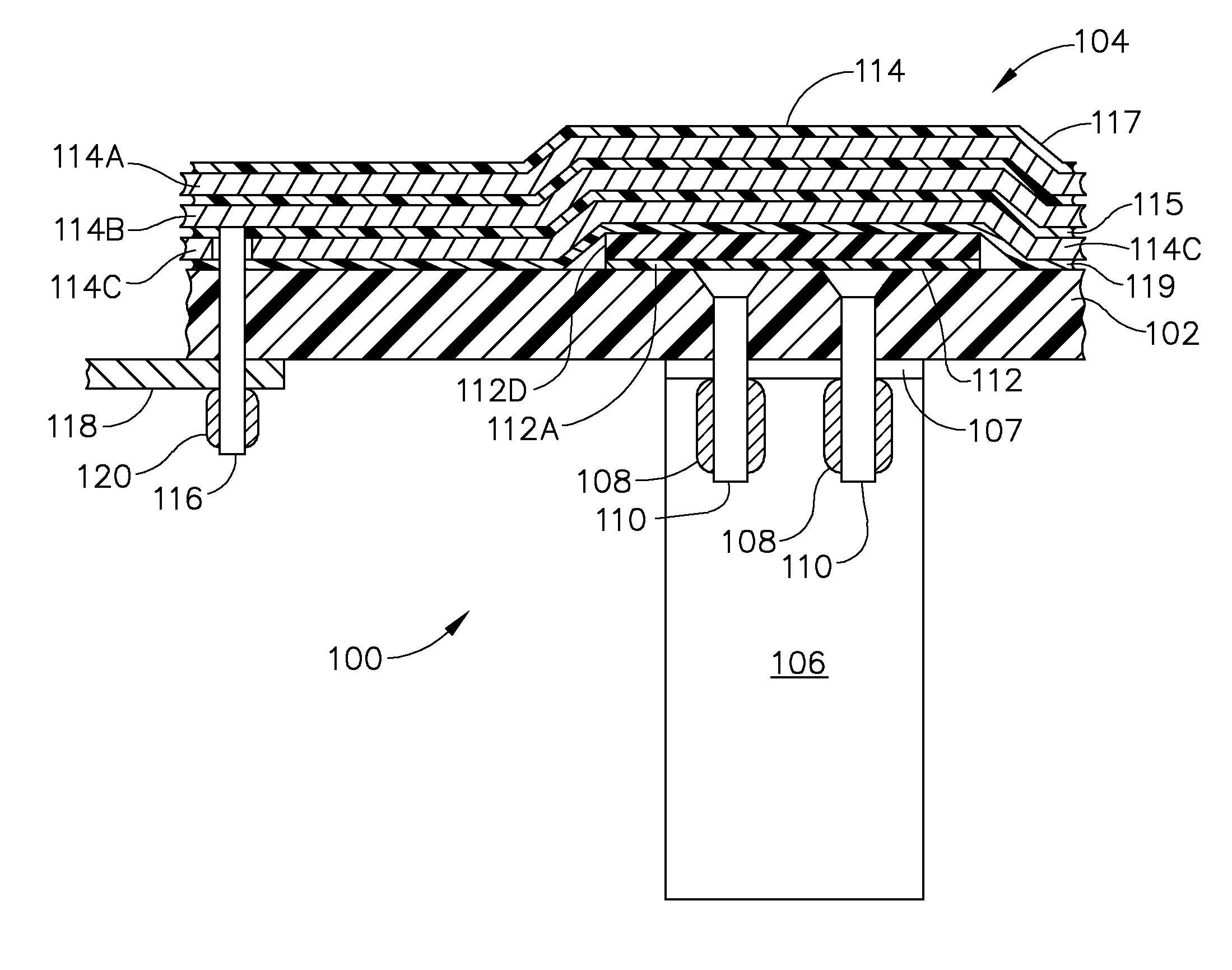
[0020]The disclosure of parent application Ser. No. 11 / 277,888, previously referenced, is incorporated herein as though fully set forth. An example of a lightning protection system according to an advantageous embodiment of the present invention is shown in FIG. 1 in a cross section 100 of an aircraft wing section. In this example, the cross section is taken through a composite skin 102, e.g., a Carbon Fiber Reinforced Plastic (CFRP) skin, of the aircraft wing, protected by an exemplary embodiment of a Flex-Circuit Lightning Protection Appliqué (FCLPA) 104. Thicknesses of the FCLPA are exaggerated for clarity. The composite skin 102 is fastened to a rib (metal or CFRP) 106 or similarly to a spar, by metallic skin fasteners 108 extending through the skin and shear tie flange 107, held in place by metallic collars or nuts 110. In this example, the cross section is part of a fuel tank housed in the wing section. Although shown in this example as protecting skin fasteners at a wing fuel...


PUM


Abstract

A lightning protection appliqué incorporates a plurality of conductive plies adhesively affixed to a composite surface, at least a first one of the plies providing conductive characteristics sufficient to divert electrical energy from a lightning strike and at least a second one of the plies comprising operational circuitry. A dielectric ply is fixed to the composite surface over and completely covering at least one metal surface feature between the plurality of conductive plies and the composite surface.

Description

REFERENCE TO RELATED APPLICATIONS[0001]This application is a continuation-in-part of U.S. patent application Ser. No. 11 / 277,888 filed on Mar. 29, 2006 now U.S. Pat. No. 7,277,266 entitled Lightning Protection System for Composite Structure having a common assignee with the present application and is related to copending U.S. application Ser. No. 10 / 941,429 published as U.S. Patent application no. 2005 / 0181203 A1 entitled Appliqué and having a common assignee with the present application.BACKGROUND OF THE INVENTION[0002]1. Field of the Invention[0003]This invention relates generally to the field of protecting composite structures from lightning strikes, and more particularly, to an appliqué having multiple conducting layers including one or more layers for protecting composite aircraft from lightning strikes and one or more layers for operational circuit functionality in aircraft systems.[0004]2. Description of the Related Art[0005]Since aluminum and other metals are highly conducti...

Claims


Application Information

Patent Timeline
Patent Type & Authority Patents(United States)
IPC IPC(8): H05F3/00H02H1/00H02H1/04H02H3/22H05F3/02B60C19/08
CPCB64D45/02H02G13/00H02G13/40H02G13/80H05K1/0393H05K1/0254
Inventor LE, QUYNHGIAO N.
Owner THE BOEING CO
Learn More