Amplitude modulation of illuminators in sensing applications in printing system

a technology of illuminators and sensing systems, applied in the direction of electrographic processes, instruments, corona discharge, etc., can solve the problems of more complex and costly sensing systems, more time-consuming sequential sampling types, and large amount of wasted documents for sensing

Inactive Publication Date: 2011-01-11
XEROX CORP
View PDF8 Cites 4 Cited by
  • Summary
  • Abstract
  • Description
  • Claims
  • Application Information

AI Technical Summary

Problems solved by technology

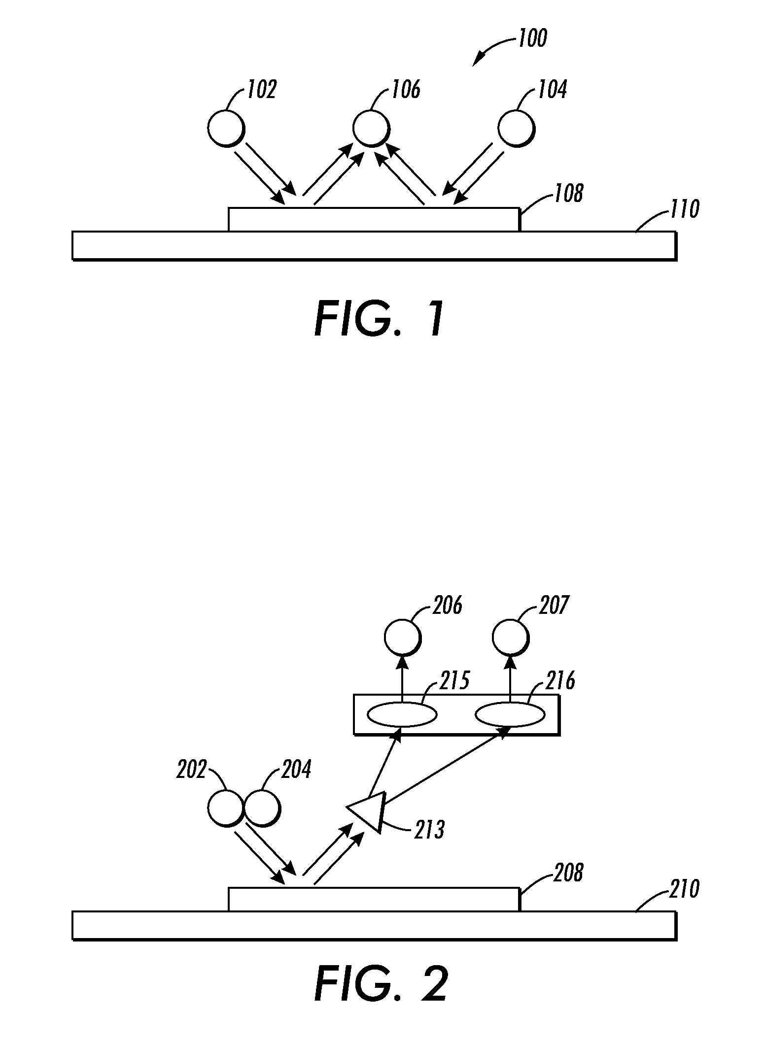
Unfortunately, this type of sequential sampling requires more time to complete than sampling with a single illuminator (N*T versus just T where N is the number of different illuminators and T is the time required to sample each illuminator).
For patches measured on customer documents, this will also require larger amounts of wasted documents for sensing.
However, there are several disadvantages associated with this second approach.
Because of these disadvantages, the second approach can result in more complex and costly sensing systems.
In addition, because of the need to split the light (e.g., using a beam splitter 213) and use optical filtering (e.g., using wavelength specific optical filters 215 and 216) to select the appropriate frequencies of interest, this second approach suffers from a higher degree of loss in illumination.
Thus, in this second approach, either stronger illuminators are required or the overall signal-to-noise ratio will likely suffer.
Another disadvantage in the second approach is that often the received signal is a function of document orientation so that a receiver design should attempt to collect light from a circularly symmetric geometry.
The second or multiple optical path approach to simultaneous illuminator sampling may not allow for this geometric design constraint to be satisfied.

Method used


Image

  • Amplitude modulation of illuminators in sensing applications in printing system
  • Amplitude modulation of illuminators in sensing applications in printing system
  • Amplitude modulation of illuminators in sensing applications in printing system

Examples


examples

[0078]The sensing technique described in the present disclosure, and the resultant gains in sampling time and / or reductions in required test patch sizes, are useful in many printing related sensing applications.

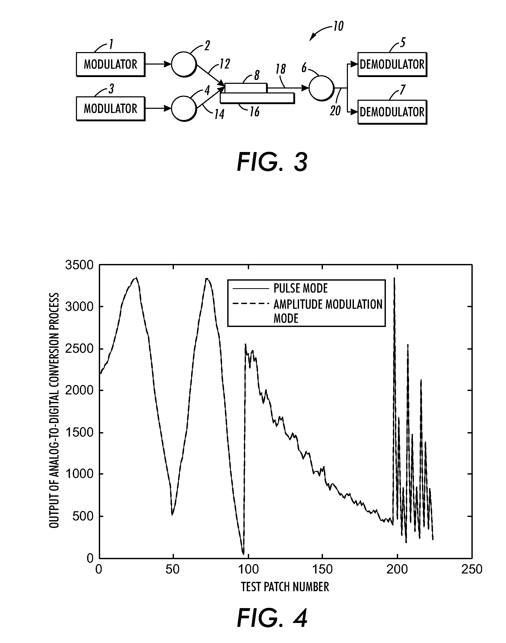
[0079]One example is a Xerox® low cost LED (LCLED) spectrophotometer. As noted above, the Xerox® LED spectrophotometer is a multiple illuminator sensing system that requires sampling of the test patch response to eight different LEDs. Currently, the sampling is performed by pulsing eight individual LEDs on one at a time and measuring the response with a single sensor, as discussed in the background section. The present disclosure instead enables sampling of the response of the test patch to all eight LEDs in a single sampling instant without adding significant additional costs to the design. Therefore, the present disclosure may provide up to a factor of eight improvement in the sampling time for this multiple illuminator sensing system. This means that an approximately 240 p...


PUM


Abstract

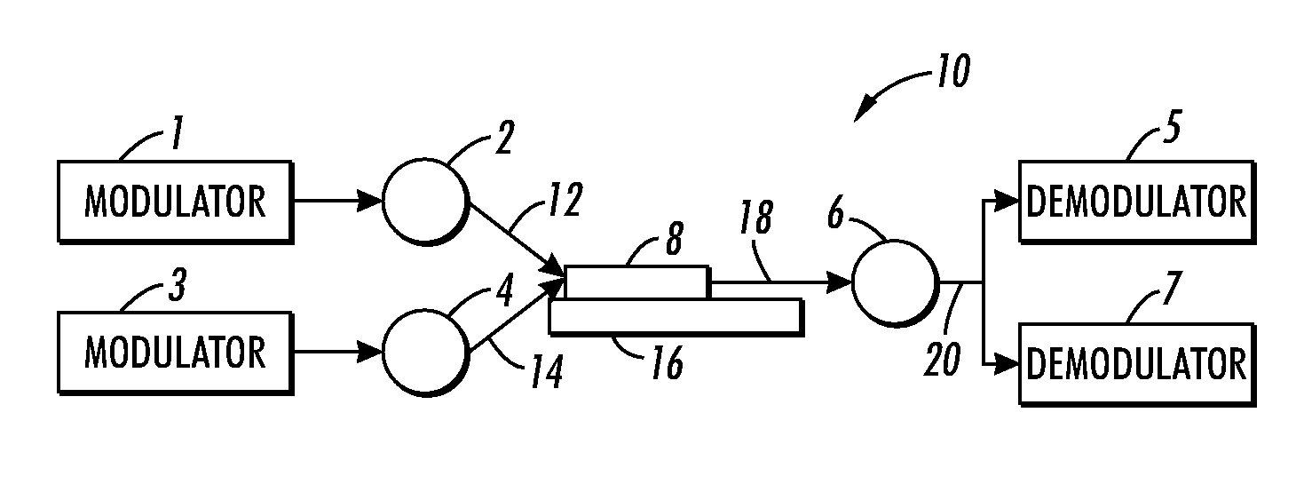
An image printing system includes a print engine and a sensing system. The print engine is configured to print a marking material image on a image bearing surface. The sensing system includes a plurality of illuminators, a modulator, a sensor, and a demodulator. Each illuminator is configured to simultaneously emit a light beam at the marking material image on the image bearing surface, thereby producing reflectance from the marking material image at least in a first direction. The modulator is configured to modulate an intensity characteristic of each of the light beams emitted by the illuminators such that each light beam has a different modulated waveform characteristic, where the waveform characteristic includes at least frequency. The sensor is configured to detect the reflectance from the plurality of light beams in the first direction and output a reflectance signal. The demodulator is configured to demodulate the reflectance signal to isolate a response of the marking material image to each of the individual illuminators.

Description

BACKGROUND[0001]1. Field[0002]This present disclosure relates to a system and a method for enabling sampling of a marking material image on a image bearing surface in response to a plurality of illuminators in an image printing system.[0003]2. Description of Related Art[0004]Optical sensors are commonly used in a variety of printing related applications. For instance, such optical sensors are often used to measure toner density on a image bearing surface (e.g. on photoreceptors, on intermediate belts, and on documents) in a printer system. Typically, sensors are designed to sample a response of a test patch on a image bearing surface to the incident light from one or more illuminators. Most of these devices make use of constant or steady illumination throughout the sampling process. In some cases, it is desirable to illuminate the test patch of interest with more than one wavelength of illumination (e.g., with three light emitting diodes (LEDs), such as red, green, and blue LEDs), o...

Claims


Application Information

Patent Timeline
Patent Type & Authority Patents(United States)
IPC IPC(8): G03G15/00G03G15/01G03G15/02
CPCG03G15/161G03G15/0131G03G15/1605G03G15/5058G03G15/5037G03G2215/00042G03G2215/00059G03G2215/0164
Inventor BURRY, AARON MICHAELLIN, JULIANNA ELIZABETHPAUL, PETER
Owner XEROX CORP
Why Eureka
Try Eureka