Elasticized side members

a technology of elastic side members and side members, which is applied in the field of side members, can solve the problems of compromising both fit and comfort, difficulty in extending the side member, reddening or abrasion of the skin, etc., and achieves the effect of promoting more uniform force distribution

Inactive Publication Date: 2011-01-18
TREDEGAR FILM PROD CORP
View PDF6 Cites 37 Cited by
  • Summary
  • Abstract
  • Description
  • Claims
  • Application Information

AI Technical Summary

Benefits of technology

[0013]In another aspect, the embodiments provide elastic side elements that are shaped and constructed to promote more uniform distribution of forces when the element is placed under tension.

Problems solved by technology

The higher extension force may make it difficult to extend the side member during the diapering process or during movement of the child while wearing the diaper, compromising both fit and comfort.
In addition, if the retraction forces of the elastic are too high, the diaper will fit too tightly, causing discomfort to the child and reddening or abrasion of the skin.
The fastening element, particularly the hook-and-loop type, is a relatively expensive component for a diaper and is a significant contributor to the overall cost of the diaper.
Furthermore, as the size of the fastening element increases, the forces necessary to disengage the element to open the diaper increase.
If those forces get too high, the outer covering of the diaper may tear or pull apart as the diaper is opened.
While this is generally not a problem with side elastic members that are closely matched to the size of the fastening element, it is problematic with elastic side members that are larger in size.
For example, it would generally be considered impractical to apply a hook-and-loop fastener to the entire width of a side component that is 100 mm in width, for example.
As a result of the uneven stresses, the portions of the elastic side member not having the fastening component tend to curl and become distorted.
Apart from an unattractive appearance, the distortion in the ear may result in improper fit of the diaper, and the diaper may fall off, leak, or have other undesirable attributes.
By switching to “stronger” elastic, the ear will be more resistant to distortion, but will also increase the cost of the diaper.
In addition, elastics that have higher elongation / retraction forces may result a diaper that is too difficult to apply (i.e., takes too much force to extend the ear) or results in reddening of the baby's skin because the retraction forces are too high.

Method used


Image

  • Elasticized side members
  • Elasticized side members
  • Elasticized side members

Examples


Embodiment Construction

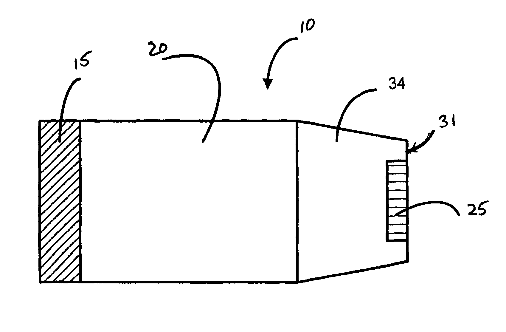
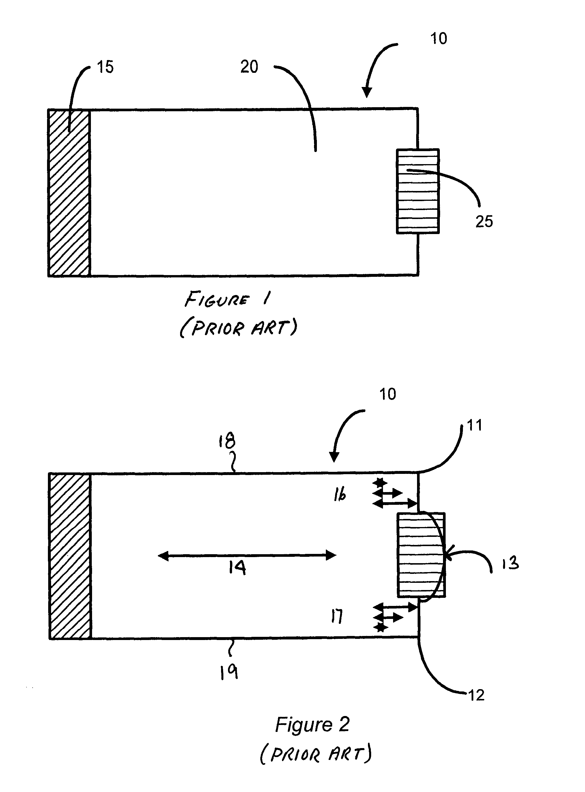
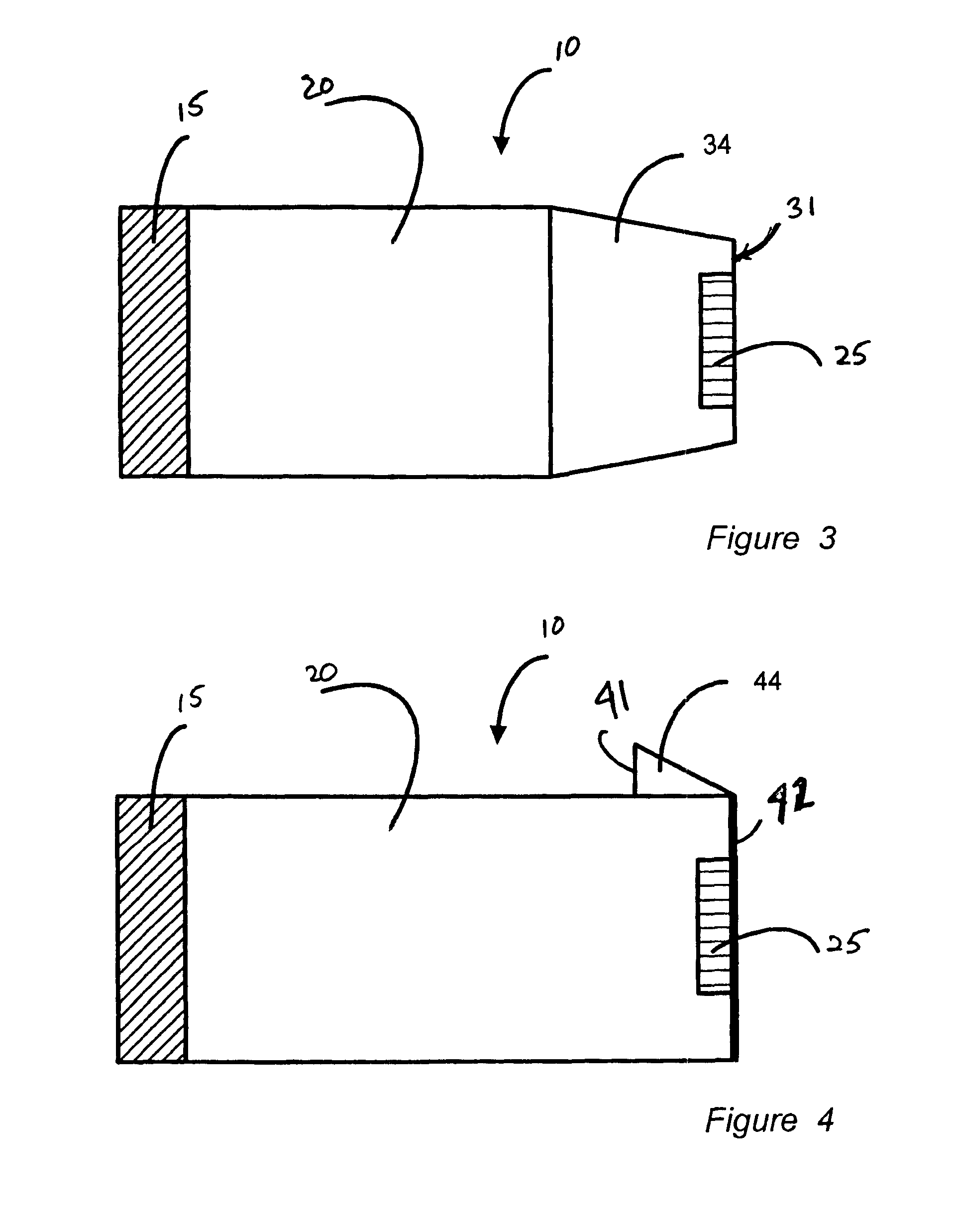
[0022]FIG. 1 is a schematic illustration of a typical prior art diaper side tab 10. The tab 10 comprises a body portion 20 which has a region 15 where the tab is attached to the chassis of a diaper (not shown). The attachment of the tab 10 to the diaper is generally accomplished by one or more bonding methods, such as adhesive bonding, thermal bonding, ultrasonic bonding, stitching, etc.

[0023]On an end of the tab 10 opposite the region 15 is a fastener 25. The fastening element is typically either an adhesive tape or a hook-and-loop type fastener, such as VELCRO®, available from Velcro USA, Inc., Manchester, N.H. The diaper is typically applied while the child is on its back. Thus, it is customary for the tab 10 to be attached at region 15 to the back portion of the diaper and for the fastener 25 to be positioned for engagement with the front of the diaper. Accordingly, the front portion of the diaper will normally be constructed with a zone adapted to cooperate with the fastener 25...


PUM


Abstract

The disclosure provides embodiments for elasticized members used as closures for garments, such as diapers, jacket cuffs, and similar articles, the elasticized member having an elastic body having an attachment region adapted for attachment of the elastic body to a garment and a fastener positioned on a distal portion of the elastic body, wherein the elastic body is structured to reduce curl along longitudinal edges and corners of the elastic body upon application of tension to the fastener.

Description

CROSS-REFERENCE TO RELATED APPLICATIONS[0001]This application claims the benefit of U.S. Provisional Application No. 60 / 790,664, filed Apr. 10, 2006 entitled DIAPER SIDE TABS AND METHODS REGARDING SAME.FIELD OF THE DISCLOSURE[0002]The present disclosure is related to side members for use in releasably fastening an article about the wearer. More specifically, the disclosure concerns elasticized side members for use in securing articles about the waist of the wearer.BACKGROUND OF THE DISCLOSURE[0003]Many articles, particularly those that are worn about the waist, include a side member that permits the article to be secured about the waist of the wearer. In baby diapers, for example, it is common to provide an elastic member containing a hook-and-loop type fastener which permits the diaper to be secured to the infant or child and, if necessary, released and re-positioned or re-fastened. These elastic members are typically attached at one end to the diaper chassis and contain the hook-a...

Claims


Application Information

Patent Timeline
Patent Type & Authority Patents(United States)
IPC IPC(8): A44B18/00
CPCA61F13/5622A61F13/62A61F13/58Y10T24/27A61F13/622
Inventor MIDDLESWORTH, JEFFREY ALANPEACOCK, ANDREW J.O'SICKEY, MATTHEW J.BRUCE, STEPHEN D.
Owner TREDEGAR FILM PROD CORP
Why Eureka
Try Eureka