Method and system for mitigating a voltage standing wave ratio

a voltage standing wave and ratio technology, applied in the field of power amplifiers, can solve the problems of restricting the range of input power levels, imposing limitations on the performance of integrated pa circuitry,

Inactive Publication Date: 2011-01-18
AVAGO TECH INT SALES PTE LTD
View PDF12 Cites 7 Cited by
  • Summary
  • Abstract
  • Description
  • Claims
  • Application Information

AI Technical Summary

Problems solved by technology

Whereas the pressing need to increase the integration of functions performed within a single IC, and attendant increase in the number of semiconductor devices, may push semiconductor fabrication technologies toward increasingly shrinking semiconductor device geometries, these very semiconductor fabrication technologies may impose limitations on the performance of the integrated PA circuitry.
For example, utilizing a 65 nm CMOS process may restrict the range of input power levels for which the PA provides linear output power level amplification.

Method used


Image

  • Method and system for mitigating a voltage standing wave ratio
  • Method and system for mitigating a voltage standing wave ratio
  • Method and system for mitigating a voltage standing wave ratio

Examples


Embodiment Construction

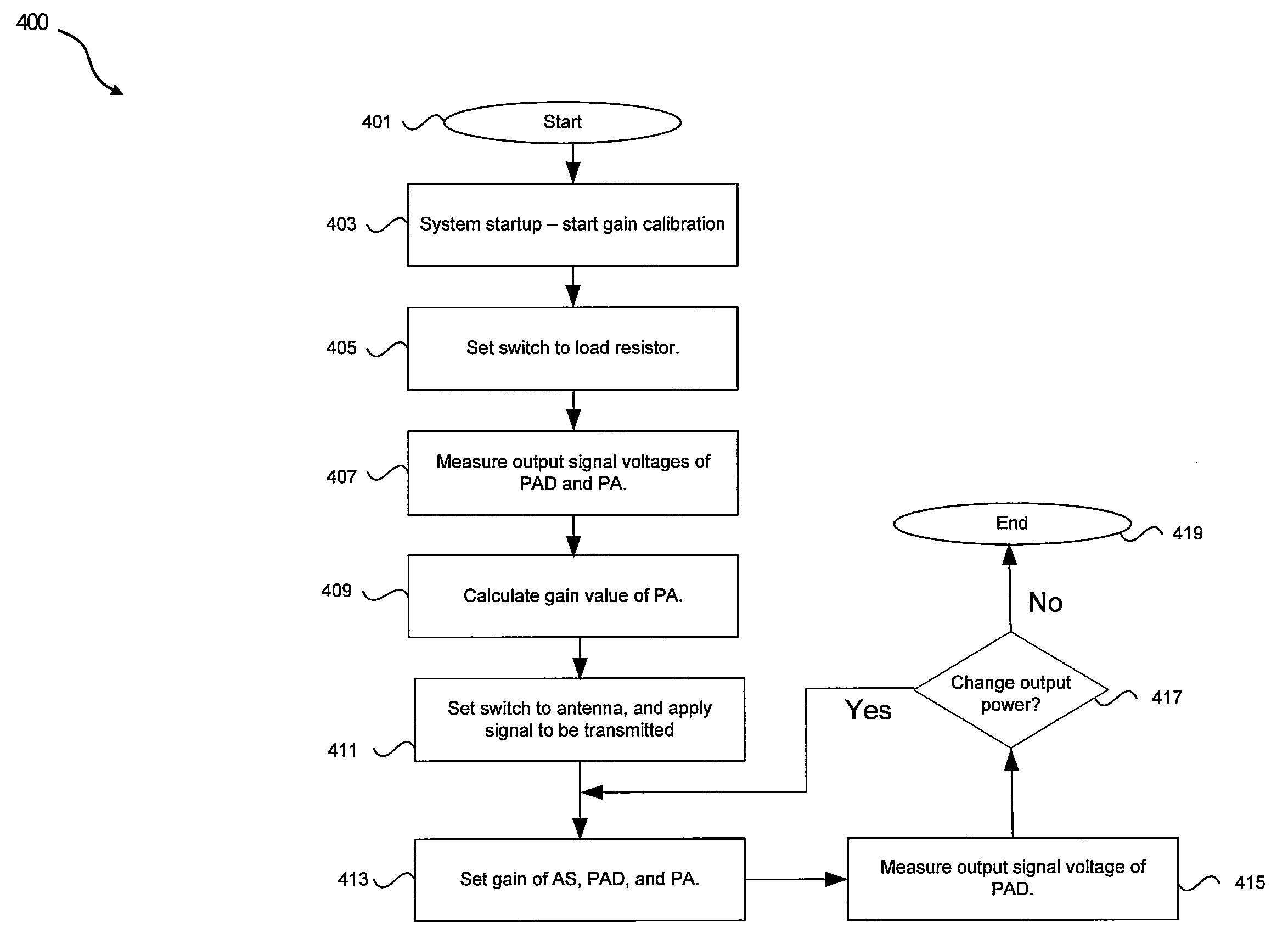
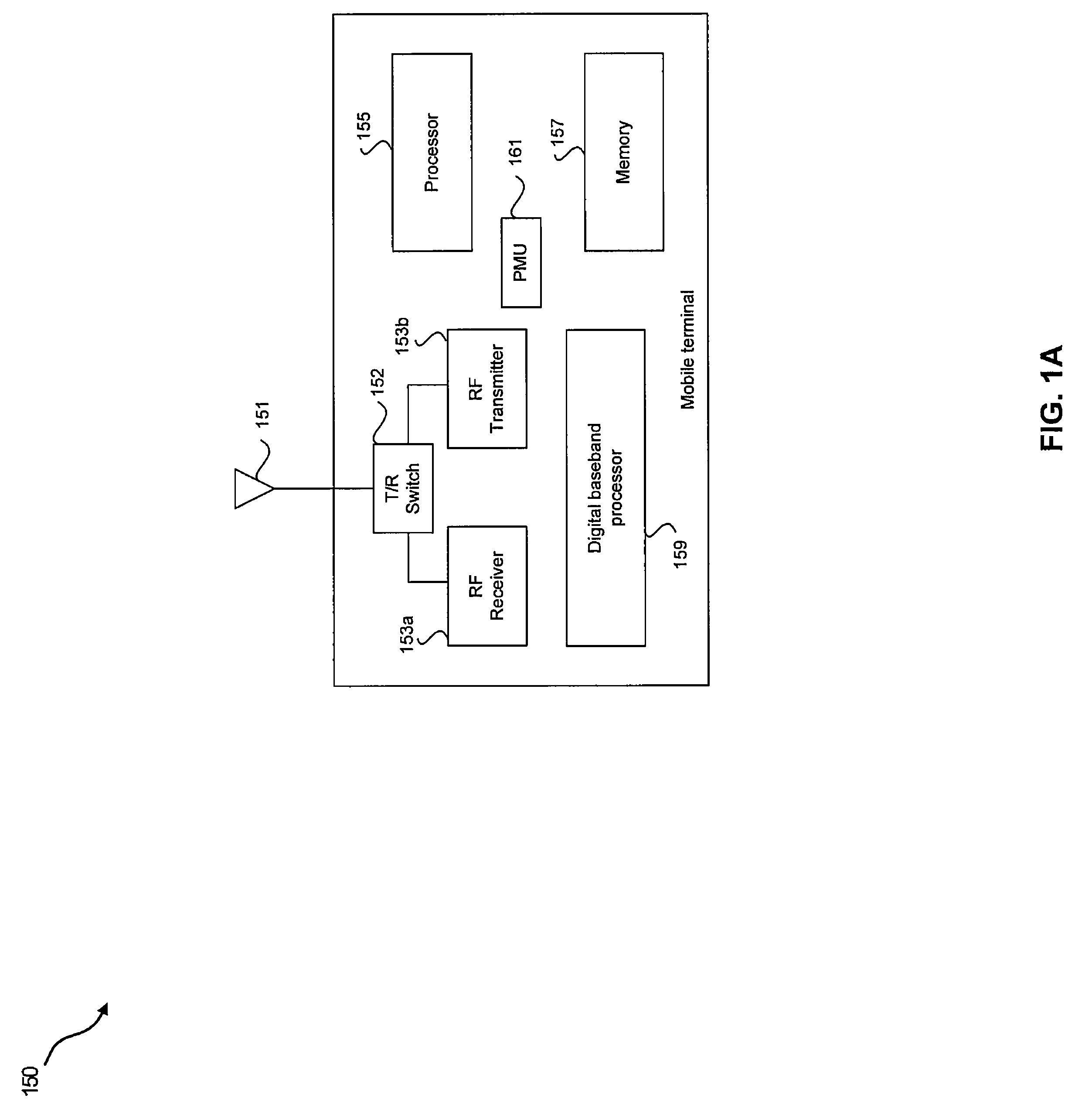
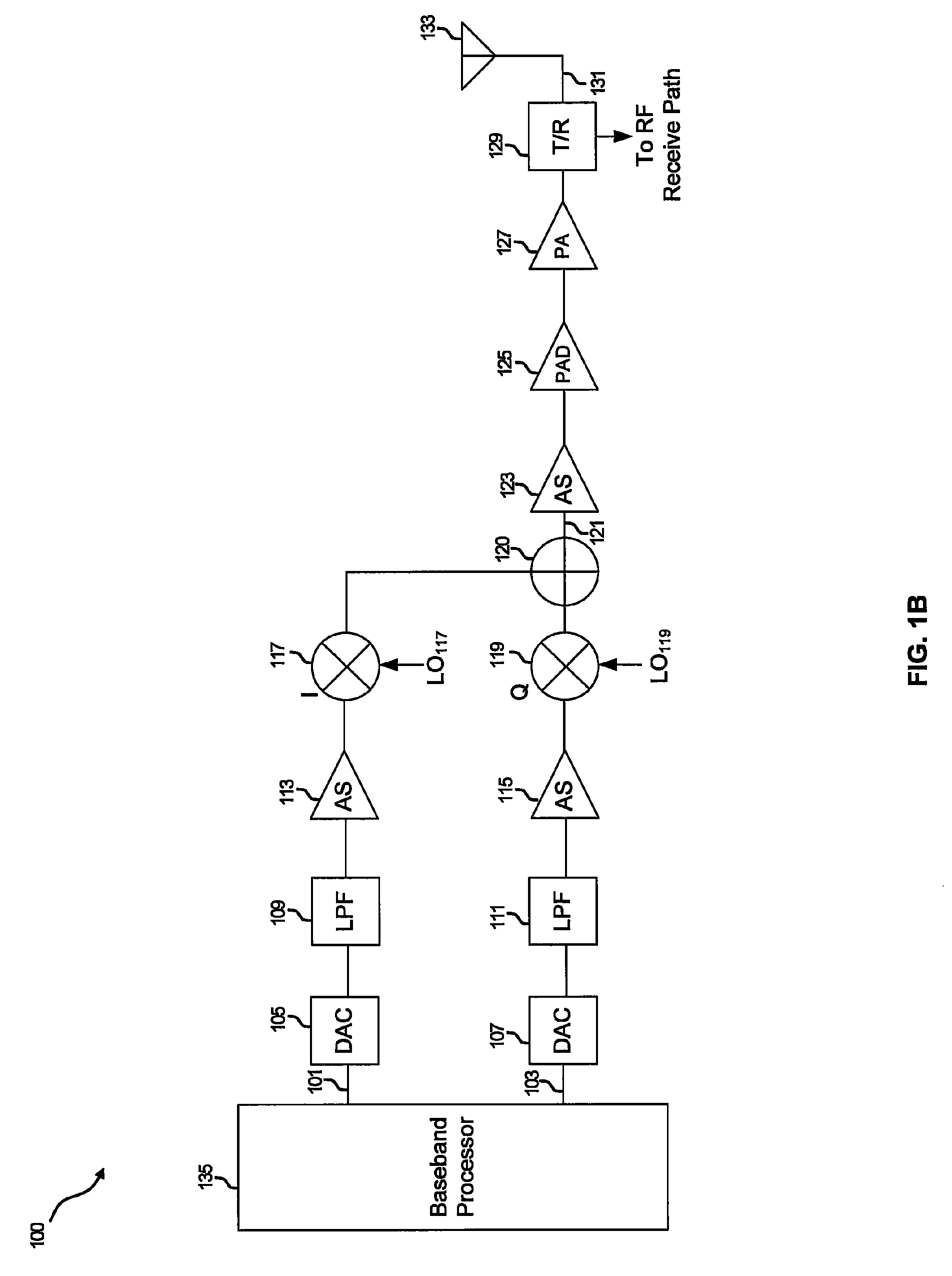
[0017]Certain aspects of the invention may be found in a method and system for controlling a circuit within a transmitter. Aspects of the invention may comprise calibrating an output power of a power amplifier integrated within a chip using an on-chip resistor that models an impedance of an antenna that is externally coupled to the amplifier while the antenna is decoupled. The gain and output power of the amplifier may be determined utilizing the known resistance and a voltage that is measured at an input of the power amplifier, or at a number of points prior to the power amplifier. When the antenna is coupled to the transmitter, the transmitter output power may then be controlled utilizing the voltage measurements prior to the power amplifier to, for example, avoid measuring reflected waves in instances when the antenna impedance may vary. The power amplifier may be of a design that comprises reverse isolation to reduce reflected waves from the antenna.

[0018]FIG. 1A is a block diag...


PUM


Abstract

Methods and systems for mitigating a voltage standing wave ratio in a transmitter are disclosed and may comprise calibrating an output power of a power amplifier integrated within a chip using a resistor that models an impedance of an antenna that is externally coupled to the amplifier while the antenna is decoupled. The gain and output power of the amplifier may be determined utilizing the known resistance and a voltage that is measured at an input of the power amplifier, or at a number of points prior to the power amplifier. When the antenna may be coupled to the transmitter, the transmitter output power may then be controlled utilizing the voltage measurements prior to the power amplifier to avoid measuring reflected waves in instances when the antenna impedance may vary. The power amplifier may be of a design that comprises reverse isolation to reduce reflected waves from the antenna.

Description

CROSS-REFERENCE TO RELATED APPLICATIONS / INCORPORATION BY REFERENCE[0001]This application makes reference to, claims priority to, and claims the benefit of U.S. Provisional Application Ser. No. 60 / 868,818, filed on Dec. 6, 2006.[0002]The above stated application is hereby incorporated herein by reference in its entirety.FEDERALLY SPONSORED RESEARCH OR DEVELOPMENT[0003][Not Applicable]MICROFICHE / COPYRIGHT REFERENCE[0004][Not Applicable]FIELD OF THE INVENTION[0005]Certain embodiments of the invention relate to power amplifiers. More specifically, certain embodiments of the invention relate to a method and system for mitigating a voltage standing wave ratio.BACKGROUND OF THE INVENTION[0006]A power amplification circuit in a wireless system is typically a large signal device. In wireless local area network (WLAN) systems, the power amplifier (PA) circuit may transmit output signals at average power levels in the range of 10 dBm to 20 dBm, and peak power levels of about 20 to 30 dBm, for ...

Claims


Application Information

Patent Timeline
Patent Type & Authority Patents(United States)
IPC IPC(8): H04B1/04
CPCH03G3/3042H03D1/00Y02D30/70
Inventor BEHZAD, ARYA
Owner AVAGO TECH INT SALES PTE LTD
Why Eureka
Try Eureka