
Methods and apparatus for communicating changes between a user-interface and an executing application, using property paths

a technology of user interface and executing application, applied in the field of client server networks, can solve the problems of exacerbated administrative burden on network administrators, limited number of applications a given client is able to execute, complex development and maintenance of applications built this way, etc., and achieve the effect of relatively straightforward design of the user interactive portion of the application

Inactive Publication Date: 2011-01-18
CITRIX SYST INC
View PDF174 Cites 105 Cited by
  • Summary
  • Abstract
  • Description
  • Claims
  • Application Information

AI Technical Summary

Benefits of technology

[0010]The present invention avoids these shortcomings. The present invention provides a mechanism by which the user-interface portion of the application can be delivered to the computer user either on the same machine on which the application is executing or on another machine remote from the machine executing the application. The invention separates the user-interface from the underlying application enabling the design of the user interactive portion of the application to be relatively straightforward.
[0011]The invention also permits the user interactive portion to be deployed on a wide range of client hardware environments without bringing with it all the required logic for performing the functionality of a particular application. These features give the user the effect of directly interacting with the application even though the application is potentially running somewhere else. User-interface, event handling and screen rendering logic stay on the client, thus dramatically reducing network traffic and latency. The invention also allows the user-interface portion to be connected with objects that do not currently exist, but may exist in the future. This makes it easier to specify connections. The invention connects the user-interface to objects using property paths. Property paths represent abstract paths and this abstract quality allows the UI to be connected to objects that may exist in the future but that do not exist at application startup or any other well defined point in time.
[0034]Some objects of this invention are as follows: to allow simple UI development for developers with little or no programming experience; to allow strong separation between application and UI development; to allow separation of UI static and dynamic aspects; to have low bandwidth and latency-tolerance communications; to allow device-clients to be tailored to the devices' capabilities; to require only a small learning curve for application and UI developers; and to allow for scalable servers.

Problems solved by technology

A related problem that occurs using this model is that the number of applications a given client is able to execute is limited due to client resource constraints.
Further, applications built this way are complex to develop and maintain and typically require modification or “porting” for all supported client computer system types.
Moreover, this technique exacerbates the administration burden on a network administrator.
This may result in perceived delays of user-interface response.
This increases the complexity of the application and prevents this technique from being useful with off-the-shelf applications.
However, this approach requires device information to be sent between the client and the server in order to maintain the client display, again introducing perceived latency into the interface.
However in using this approach, information sent from the server application to the client begins to “age” immediately.
Further, with this approach, interactivity requires context switching between pages even to perform simple tasks.
This coordination becomes very difficult as the number of pages or the number of clients increases.

Method used


Image

  • Methods and apparatus for communicating changes between a user-interface and an executing application, using property paths
  • Methods and apparatus for communicating changes between a user-interface and an executing application, using property paths
  • Methods and apparatus for communicating changes between a user-interface and an executing application, using property paths

Examples


Embodiment Construction

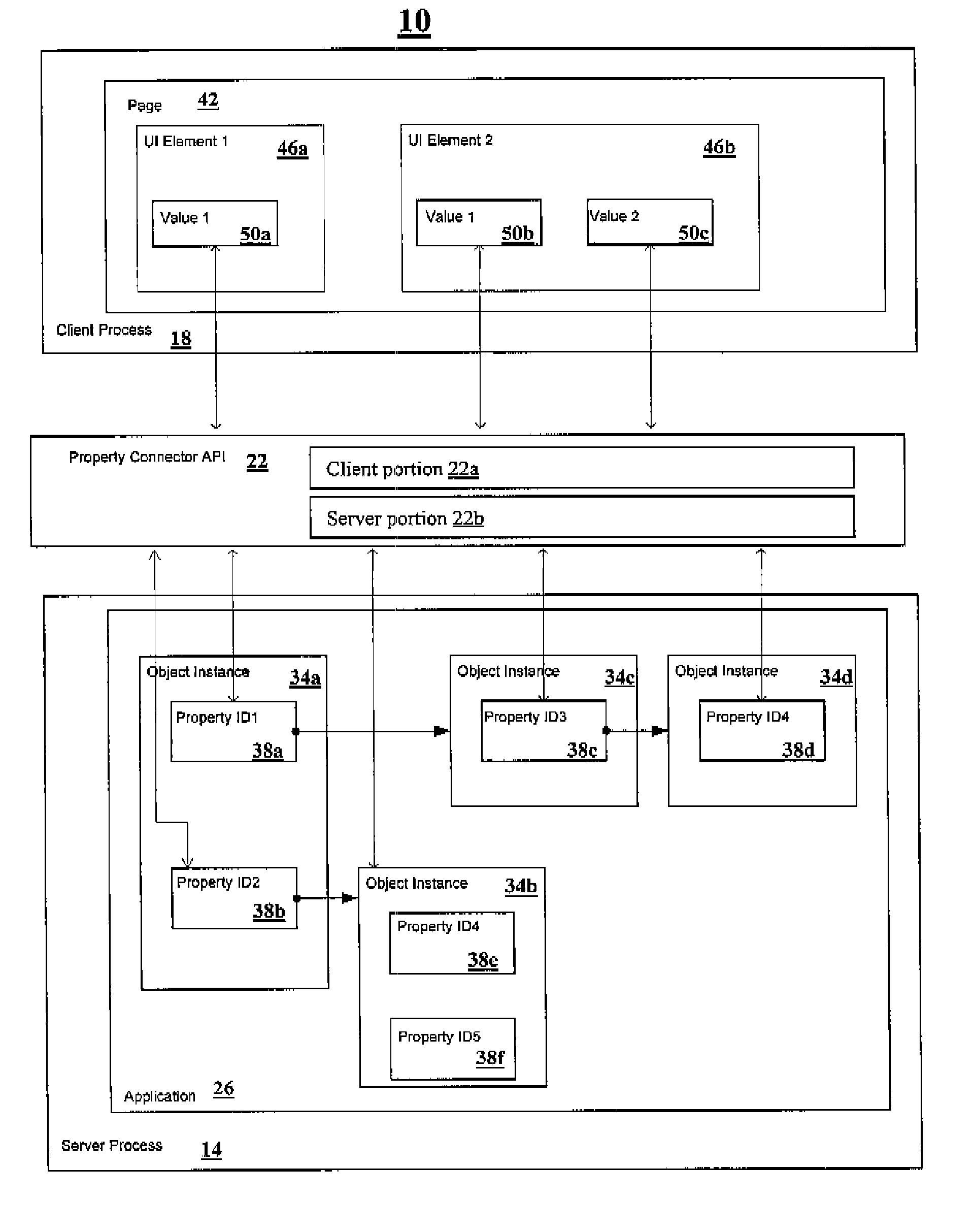
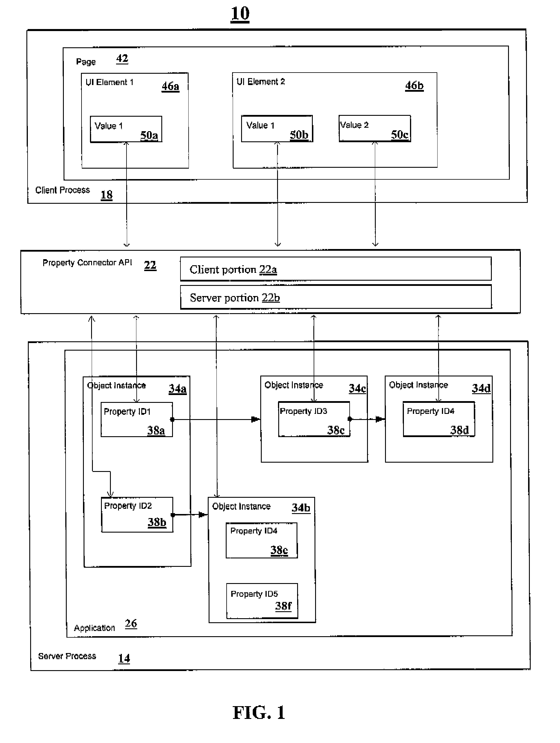
[0049]FIG. 1 depicts a block diagram of an embodiment of a system 10 for communicating changes between a user-interface and an executing application, using property paths. The system 10 includes a server process 14, a client process 18 and a property connector API 22. The server process 14, the client process 18 and the property connector API 22 can be located on a single computing device or distributed among several computing devices. The server process 14 includes an application 26 with application components 34a, 34b, 34c and 34d (generally 34). In this embodiment, the application components 34a, 34b, 34c and 34d are instances of objects that the application 26 generates.

[0050]Each of the application components 34a, 34b, 34c and 34d includes zero or more properties 38a, 38b, 38c, 38d, 38e and 38f (generally 38). This embodiment includes two types of properties. A first type of properties 38, for example, 38d, 38e and 38f, have a value for a specific variable. A second type of pro...


PUM


Abstract

A method for detecting a change in a current state of a property associated with an element of a user-interface includes the step of associating the element with a property path including a concatenation of a plurality of identifiers defining a path through a plurality of application components to a property at the end of the concatenation. The property path is mapped to a current state of the property at the end of the path. A request is received, from a local machine, for a change in a state of a property mapped to one of said plurality of concatenated identifiers defining the property path. The request for the change is sent to a remote machine. The remote machine applies the change. The local machine updates the element of the user-interface associated with the property path responsive to the change and the received regeneration.

Description

CROSS-REFERENCE TO RELATED APPLICATIONS[0001]The present application claims priority to U.S. patent application No. 09 / 846,896, entitled “Methods and Apparatus for Communicating Changes Between a User-Interface and an Executing Application, Using Property Paths,” filed May 1, 2001, which is incorporated herein by reference.FIELD OF THE INVENTION[0002]The present invention relates to client-server networks and, in particular, to methods and apparatus for communicating changes between a user interface and an executing application.BACKGROUND OF THE INVENTION[0003]Contemporary computer networks consist of a number of computer systems, called nodes, communicating with other computer systems via communication links. Typically, some of the nodes are client nodes and other nodes are server nodes. A client node formulates and delivers queries to a server node. A user of the client node enters the queries through a user-interface operating on the client node. The server node evaluates the que...

Claims


Application Information

Patent Timeline
Patent Type & Authority Patents(United States)
IPC IPC(8): G06F3/00G06F9/46G06F9/44G06F13/00G06F15/16H04L12/00
CPCG06F8/38G06F9/4443G06F9/542G06F2209/544G06F2209/545G06F9/451
Inventor HAYTON, RICHARDOTWAY, DAVID JOHN
Owner CITRIX SYST INC
Learn More