Optical pickup device and optical disc drive apparatus

a pickup device and optical disc technology, applied in the field of thin optical pickup devices, can solve the problems of increased cost, increased manufacturing costs, and difficulty in assembly, and achieve the effects of preventing damage to the objective lens, reducing the cost of the optical pickup device, and easy formation of a disc protector (or contact preventing member)

Inactive Publication Date: 2011-01-18
HITACHI MEDIA ELECTORONICS CO LTD
View PDF9 Cites 9 Cited by
  • Summary
  • Abstract
  • Description
  • Claims
  • Application Information

AI Technical Summary

Benefits of technology

[0014]The present invention has been devised to solve the above problems. It is, therefore, an object of the present invention to provide a low cost, high reliability optical pickup device employing a disc protector that is formed of only inexpensive adhesives but that has equal or higher functionality than conventional disc protectors and is easy to fabricate. Another object of the present invention is to provide an optical disc drive apparatus incorporating such an optical pickup device.
[0020]The present invention enables one to easily form a disc protector (or contact preventing member) of an optical pickup device at low coat. The disc protector prevents damage to the objective lens and the optical disc when the focus servo system of the actuator portion does not function as intended or when a strong force is applied to the optical pickup device. This allows a significant reduction in the cost of the optical pickup device and hence the cost of optical disc drive apparatuses incorporating such an optical pickup device.

Problems solved by technology

Although the above conventional optical pickup devices have satisfactory performance, it is very difficult to assemble them, that is, their manufacture requires an increased number of processes.
Further, a special resin material must be used to form the protector member(s), resulting in increased cost.
However, adhesives have tackiness and have a high friction coefficient and poor surface slipperiness, as compared to POM and the special fluorine-based resin material described above (which have a low friction coefficient and very high surface slipperiness).
In this case, however, the adhesive still has a higher friction coefficient than the above special resins (which have a low friction coefficient and very high surface slipperiness).
Furthermore, the high hardness of the adhesive (or lens protector) may result in damage to the surface of the optical disc.
In such a case, however, the adhesive has increased tackiness and hence an increased friction coefficient, resulting in an increase in the frictional force on the adhered portion.
Furthermore, if a shock is imparted to the optical pickup device, the lens protector may collide with the lens holder or the objective lens since it has a reduced hardness (as described above), resulting in damage to the lens holder or the objective lens.
That is, unlike the above molding resins, no single adhesive can provide both the required surface slipperiness and the required characteristics for collision prevention at the same time.
However, like the above POM material and special fluorine-based resin material, such a molded body is very costly, as compared to adhesives, etc., and furthermore is difficult to accurately mount on the lens holder.

Method used


Image

  • Optical pickup device and optical disc drive apparatus
  • Optical pickup device and optical disc drive apparatus
  • Optical pickup device and optical disc drive apparatus

Examples


first embodiment

[0046]A first embodiment of the present invention will be described with reference to FIGS. 1 to 5.

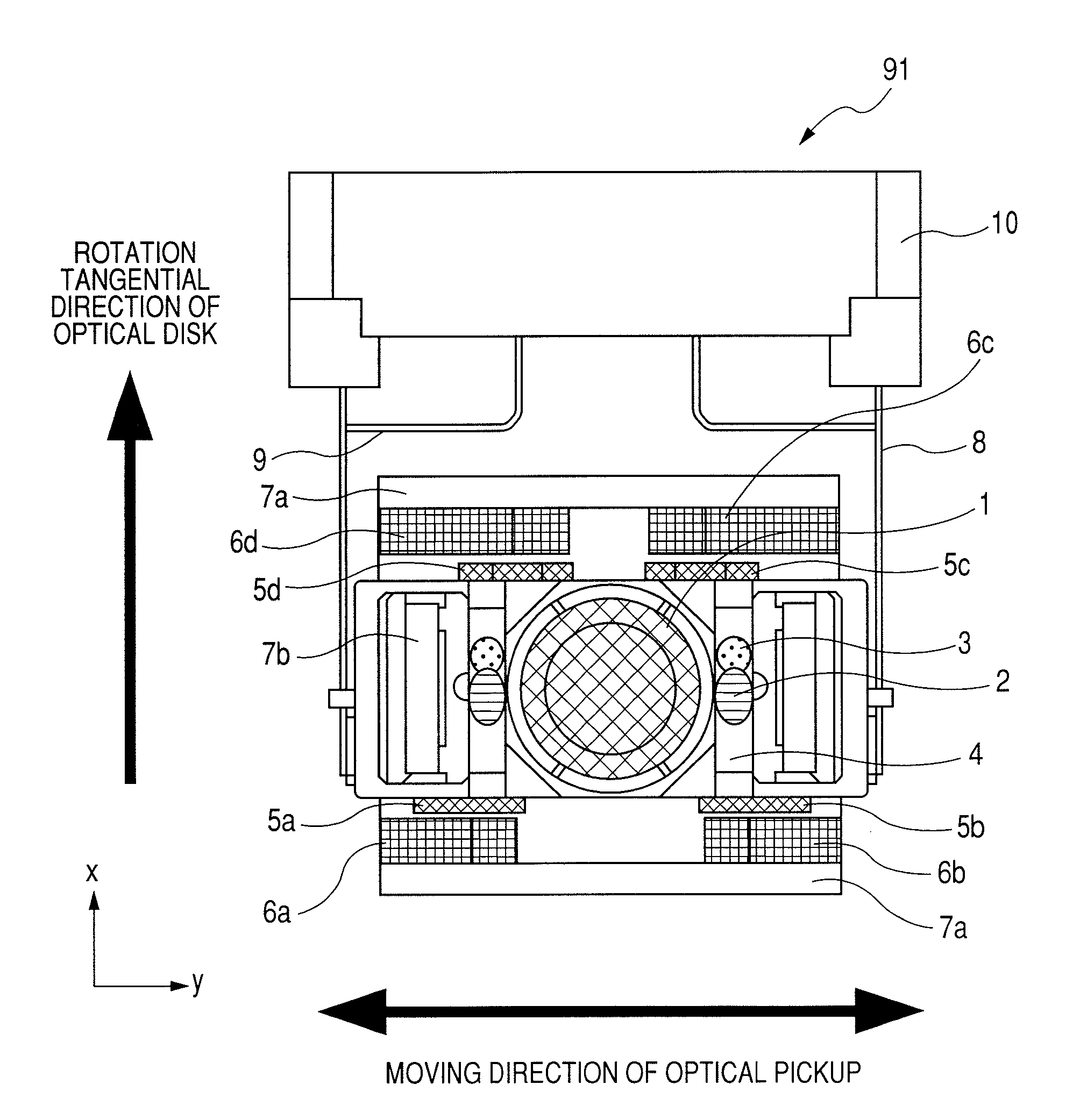
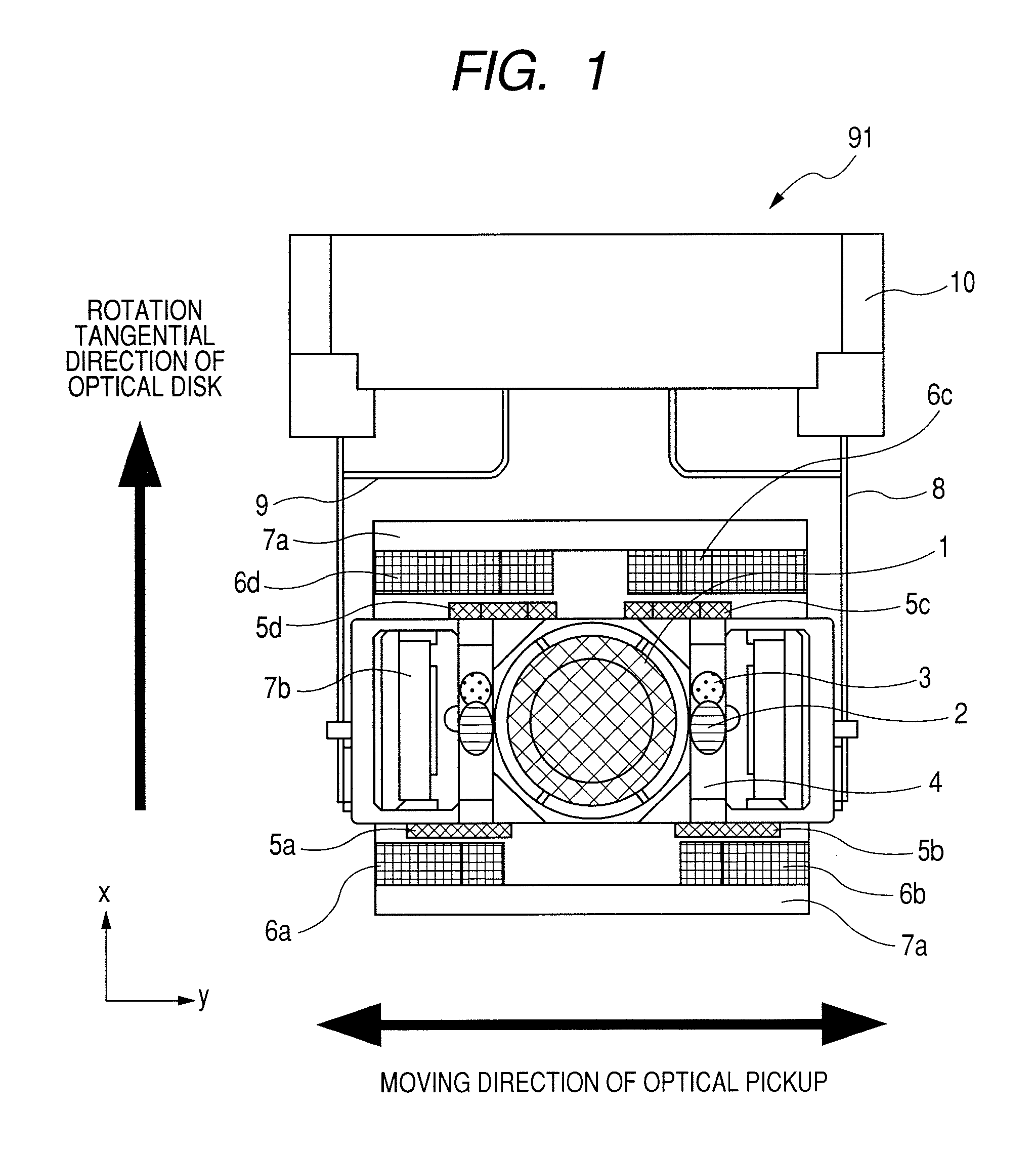
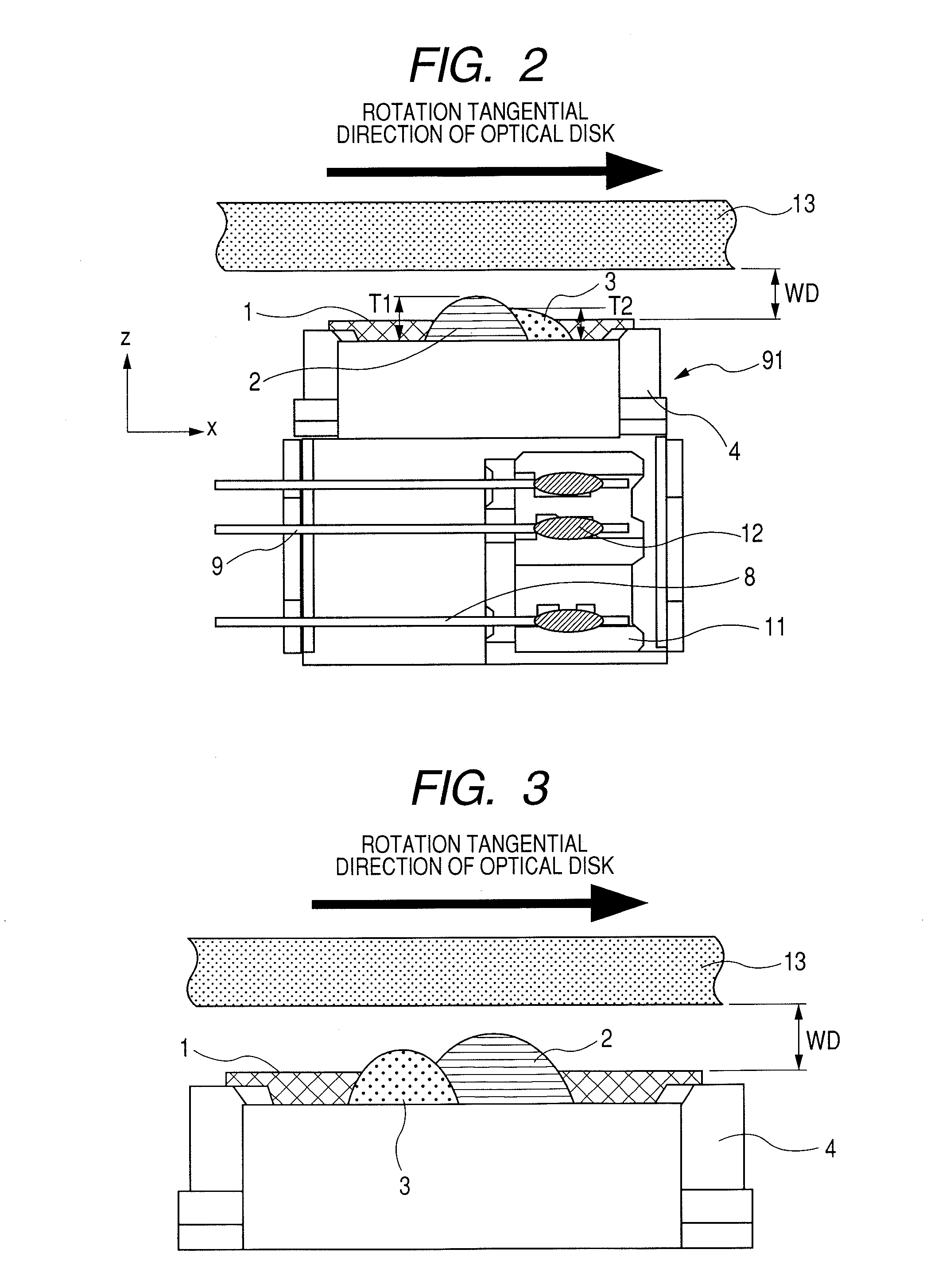
[0047]FIG. 1 is a top view and FIG. 2 is a side view of an actuator portion according to the first embodiment of the present invention. Referring to FIGS. 1 and 2, a lens holder 4 has mounted thereon an objective lens 1, first protrusions 2 formed of a first adhesive, second protrusions 3 formed of a second adhesive, an AF coil (not shown), and TR coils 5 (5a to 5d). The lens holder 4 is attached to a dumping holder 10 by a suspension wire 8 and a T wire 9. The above attaching members are formed of various adhesives and solder. As shown in the side view of FIG. 2, the first protrusions 2, which are formed of the first adhesive, protrude toward the optical disc 13 (upward) and have a height (or thickness) T1 of approximately 0.25 mm. The second protrusions 3, which are formed of the second adhesive, also protrude toward the optical disc 13 (upward) and have a height (or thickness) T2 of...

second embodiment

[0055]A second embodiment of the present invention will be described with reference to FIGS. 6 and 7. FIGS. 6 and 7 are side views of actuator portions according to the second embodiment of the present invention. The actuator portions of the present embodiment differ from those of the first embodiment in that the second protrusions 3 are first formed by application of the second adhesive before forming the first protrusions 2 by application of the first adhesive. This approach may be advantageous depending on the types of adhesive materials used. For example, UV cure adhesives and thermosetting adhesives generally tend to exhibit poor adhesion to silicone resins (or silicone-based adhesives). On the other hand, silicone resins may exhibit good adhesion to UV cure adhesives and thermosetting adhesives. Therefore, when the first adhesive is a condensation-polymerized silicone resin (a silicone-based adhesive), the second adhesive (a UV cure adhesive or a thermosetting adhesive) may be...

third embodiment

[0057]A third embodiment of the present invention will be described with reference to FIGS. 8 to 10. FIGS. 8 to 10 are side views of actuator portions according to the third embodiment of the present invention. The actuator portions of the present embodiment differ from those of the first and second embodiments in that the area to which the first adhesive is applied includes a convex portion 2a or a concave portion 2b or 2c, as shown in FIGS. 8 to 10. These convex and concave portions can be used to position the first adhesive when it is applied to the lens holder 4. Especially, the concave portions 2b and 2c may be grooves that extend in the direction of movement of the optical pickup device and pass through opposing sides of the lens holder 4 that sandwich the objective lens 1. This arrangement is preferred since it facilitates escape of moisture and irradiation of the adhesive with UV light. This prevents any portion of the adhesive from being left unhardened, or reduces the time...


PUM

PropertyMeasurementUnit
thicknessaaaaaaaaaa
thicknessaaaaaaaaaa
particle sizeaaaaaaaaaa

Abstract

The present invention provides an optical pickup device employing a disc protector that includes a plurality of first protrusions and at least one second protrusion disposed on the lens holder, wherein the first protrusions are formed by applying a first adhesive to a plurality of areas of a top surface of the lens holder, wherein the first protrusions are arranged at different locations in the tracking direction such that the objective lens is sandwiched between the first protrusions, wherein the at least one second protrusion protrudes is formed by applying a second adhesive to at least one area of the top surface of the lens holder, and wherein tips of the first protrusions are closer to the optical disc than a tip of the at least one second protrusion.

Description

[0001]The present application claims priority from Japanese application JP2006-227529 filed on Aug. 24, 2006, the content of which is hereby incorporated by reference into this application.BACKGROUND OF THE INVENTION[0002]1. Field of the Invention[0003]The present invention relates to thin optical pickup devices (sometimes referred to as slim or ultra-slim optical pickup devices) for writing to and reading from an optical disc such as a CD (compact disc), DVD (digital versatile disc), etc., and relates to optical disc drive apparatuses incorporating such a thin optical pickup device. The invention also relates to optical pickup devices for writing to and reading from an optical recording medium such as a Blu-ray disc (for use in a blue semiconductor laser), HD-DVD, etc., and relates to optical disc drive apparatuses incorporating such an optical pickup device.[0004]2. Description of the Related Art[0005]The following describes the inner workings of an optical pickup device for writi...

Claims


Application Information

Patent Timeline
Patent Type & Authority Patents(United States)
IPC IPC(8): G11B7/00
CPCG11B7/1201G11B7/08582G11B7/121
Inventor ARAI, SATOSHIFURUICHI, HIROAKIOOZEKI, YOSHIONOMURA, RIKAOKAMURA, MASAYUKITAKAHASHI, KAZUMISATAKE, MITSUO
Owner HITACHI MEDIA ELECTORONICS CO LTD
Why Eureka
Try Eureka