[0015]In the installation structure of the construction of the above Paragraph (1), the electric connection box which is electrically connected to the electrical equipment of the automobile via the wire harness is installed at the center cluster provided at the central portion of the instrument panel of the automobile, and therefore the disposition of the electric connection box is effective particularly in laying out the wire harness (which connects the electrical equipment within the instrument panel to the electric connection box) short. And besides, since the electric connection box is disposed at the central portion of the instrument panel, wire harnesses can be installed to extend the shortest and equal lengths from the electric connection box, for example, respectively to two (left and right) electrical equipments of the same type, located respectively at left and right positions disposed line-symmetrically within the automobile, so as to electrically connect the electric connection box to the two electrical equipments. With this arrangement, DC resistances of conductors of the wire harnesses are made equal to each other, and this is very suitable for those electrical equipments which do not like a situation in which a potential difference develops due to the slight difference between the DC resistances of the conductors. Furthermore, the wire harnesses can be arranged to have the shortest and equal lengths, respectively, and therefore not only a material cost of the wire harnesses but also the kinds of the wire harnesses can be reduced, and therefore this is desirable from the viewpoint of the reduction of the costs.
[0016]In the installation structure of the construction of the above Paragraph (2), the electric connection box includes the switch for controlling the electrical equipment, and the operating portion of the switch is exposed to form part of the design surface of the center cluster, and therefore the electric connection box can be suitably integrated with the center cluster which is important for the aesthetic appearance of the instrument panel and also for the operation of the electrical equipment. Therefore, a compact design of the instrument panel as a whole can be achieved.
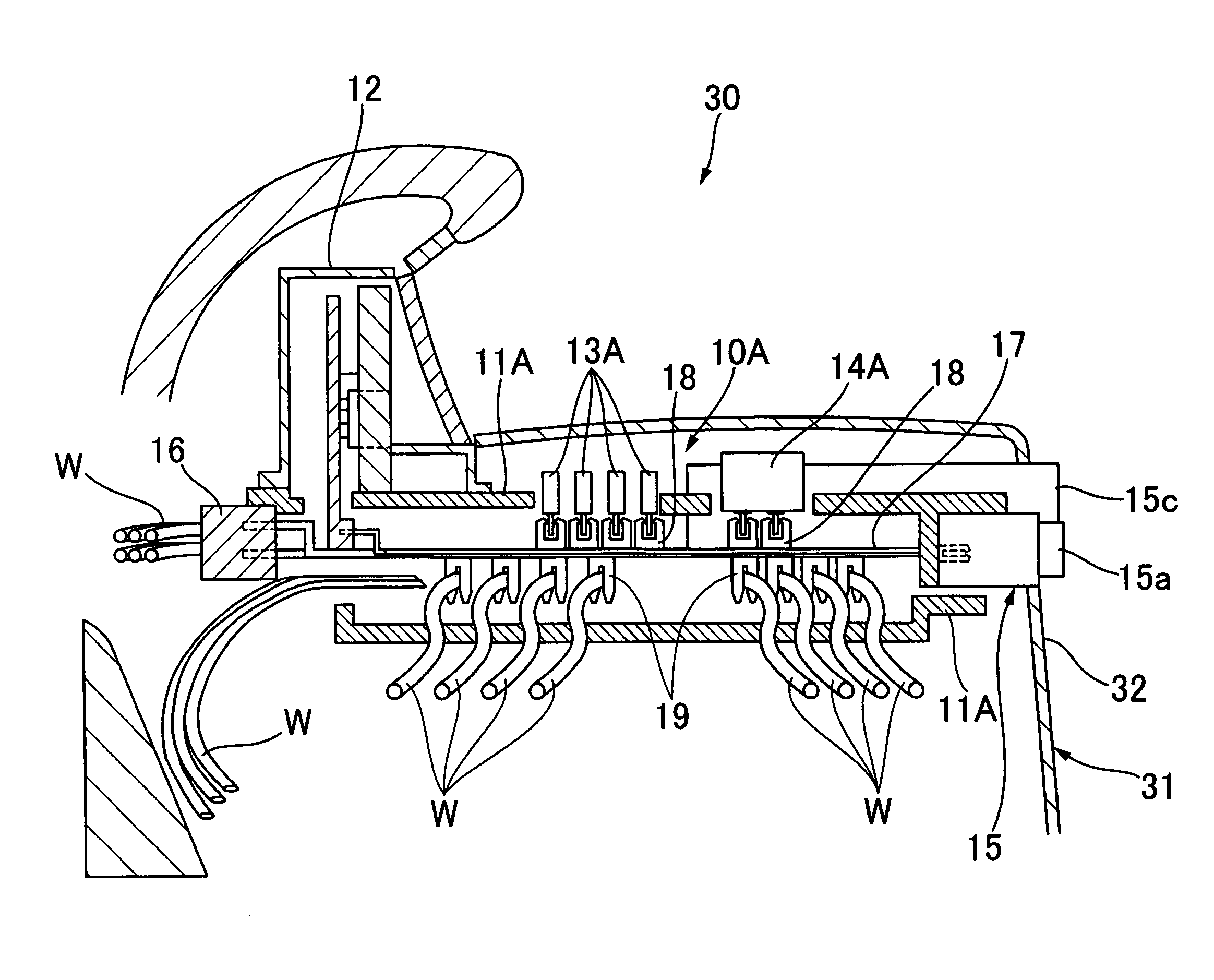
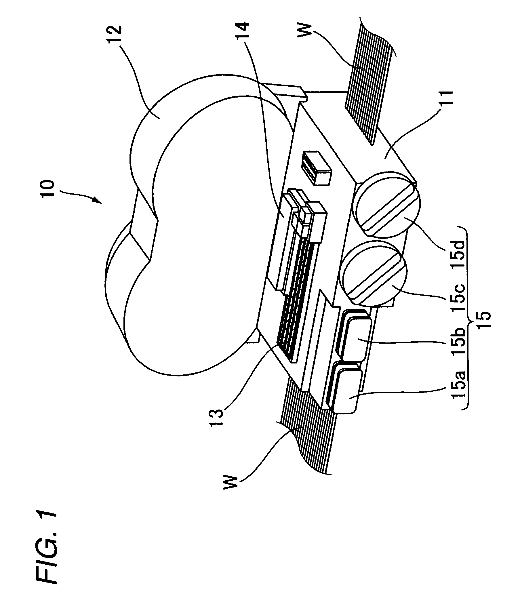
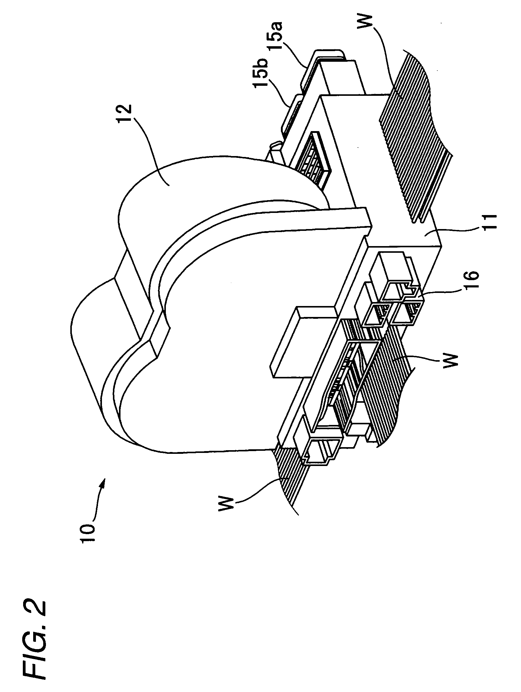
[0022]The electric connection box of the construction of the above Paragraph (3) is installed at the center cluster provided at the central portion of the instrument panel, and is electrically connected to the electrical equipment of the automobile via the wire harness. Therefore, the electric connection box is disposed at such a portion of the instrument panel that particularly the wire harness for connecting the electrical equipment within the instrument panel to the electric connection box can be effectively laid out short. And besides, since the electric connection box is disposed at the central portion of the instrument panel, wire harnesses can be installed to extend the shortest and equal lengths from the electric connection box, for example, respectively to two (left and right) electrical equipments of the same type, located respectively at left and right positions disposed line-symmetrically within the automobile, so as to electrically connect the electric connection box to the two electrical equipments. With this arrangement, DC resistances of conductors of the wire harnesses are made equal to each other, and this is very suitable for those electrical equipments which do not like a situation in which a potential difference develops due to the slight difference between the DC resistances of the conductors. Furthermore, the wire harnesses can be arranged to have the shortest and equal lengths, respectively, and therefore not only the material cost of the wire harnesses but also the kinds of the wire harnesses can be reduced, and therefore this is desirable from the viewpoint of the reduction of the costs. Furthermore, the electric connection box of the construction of the above Paragraph (3) has the surface forming part of the design surface of the center cluster, and therefore the electric connection box can be suitably integrated with the center cluster which is important for the aesthetic appearance of the instrument panel and also for the operation of the electrical equipments. Therefore, a compact design of the instrument panel as a whole can be achieved.
[0023]The electric connection box of the construction of the above Paragraph (4) further includes the switch for controlling the electrical equipment, and the operating portion of the switch is exposed at the surface forming part of the design surface of the center cluster. Therefore, the electric connection box can be more suitably integrated with the center cluster which is important for the aesthetic appearance of the instrument panel and also for the operation of the electrical equipments. Therefore, the compacter design of the instrument panel as a whole can be achieved.
[0024]In the present invention, there can be provided the electric connection box-installation structure and the electric connection box, in which the wire harness can be laid out as short as possible.
