Organic light emitting diode module

a light-emitting diode module and organic technology, applied in the direction of discharge tube/lamp details, thermoelectric devices, discharge tubes luminescnet screens, etc., can solve the problems of significant thickness of connectors, and high cost of flexible printed circuit boards. achieve uniform brightness, reduce material cost, and reduce the effect of cos

Active Publication Date: 2014-05-06
OPTRONIC SCI LLC
View PDF5 Cites 1 Cited by
  • Summary
  • Abstract
  • Description
  • Claims
  • Application Information

AI Technical Summary

Benefits of technology

[0027]In the aforementioned embodiments of the present invention, since the cross connection conductor of the organic light emitting diode module is electrically connected to the second copper foils, an end of a conductive wire can be selectively electrically connected to one of the cross connection conductor and the second copper foils, and another end of the conductive wire is electrically connected to an anode of the power supply, such that the power supply can provide the positive potential to the second copper foils at the same time. Moreover, two ends of another conductive wire can be connected respectively to the first copper foil and a cathode of the power supply, such that the power supply can provide the negative potential to the first copper foil. As a result, the organic light emitting diode module in the aforementioned embodiments can have uniform brightness by only the two conductive wires connected to the power supply, and the cost of the copper foils is cheaper than the cost of conventional flexible printed circuit boards, such that the material cost and the assembly cost of the organic light emitting diode module can be reduced. Furthermore, the copper foils can be connected to the conductive wires without any connectors (e.g., by soldering), such that the thickness of the organic light emitting diode module can be decreased.

Problems solved by technology

However, the cost of the flexible printed circuit board is high, and the thickness of the connector is significant (more than 2.5 mm).
The thickness of the connector is such that the thickness of the whole organic light emitting diode module is not easily reduced.
Furthermore, the conventional organic light emitting diode module needs the four conductive wires to connect to the four flexible printed circuit boards, such that the cost of assembling the organic light emitting diode module is increased.

Method used


Image

  • Organic light emitting diode module
  • Organic light emitting diode module
  • Organic light emitting diode module

Examples


Embodiment Construction

[0040]In the following detailed description, for purposes of explanation, numerous specific details are set forth in order to provide a thorough understanding of the disclosed embodiments. It will be apparent, however, that one or more embodiments may be practiced without these specific details. In other instances, well-known structures and devices are schematically shown in order to simplify the drawings.

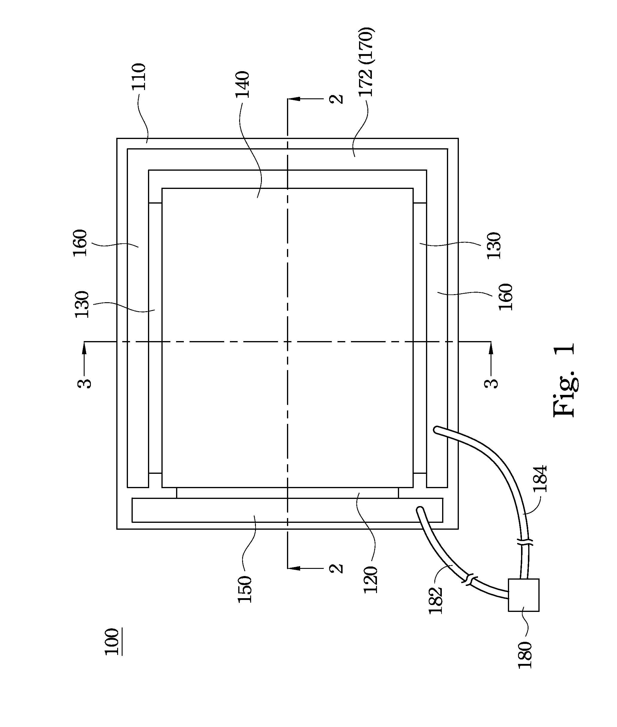
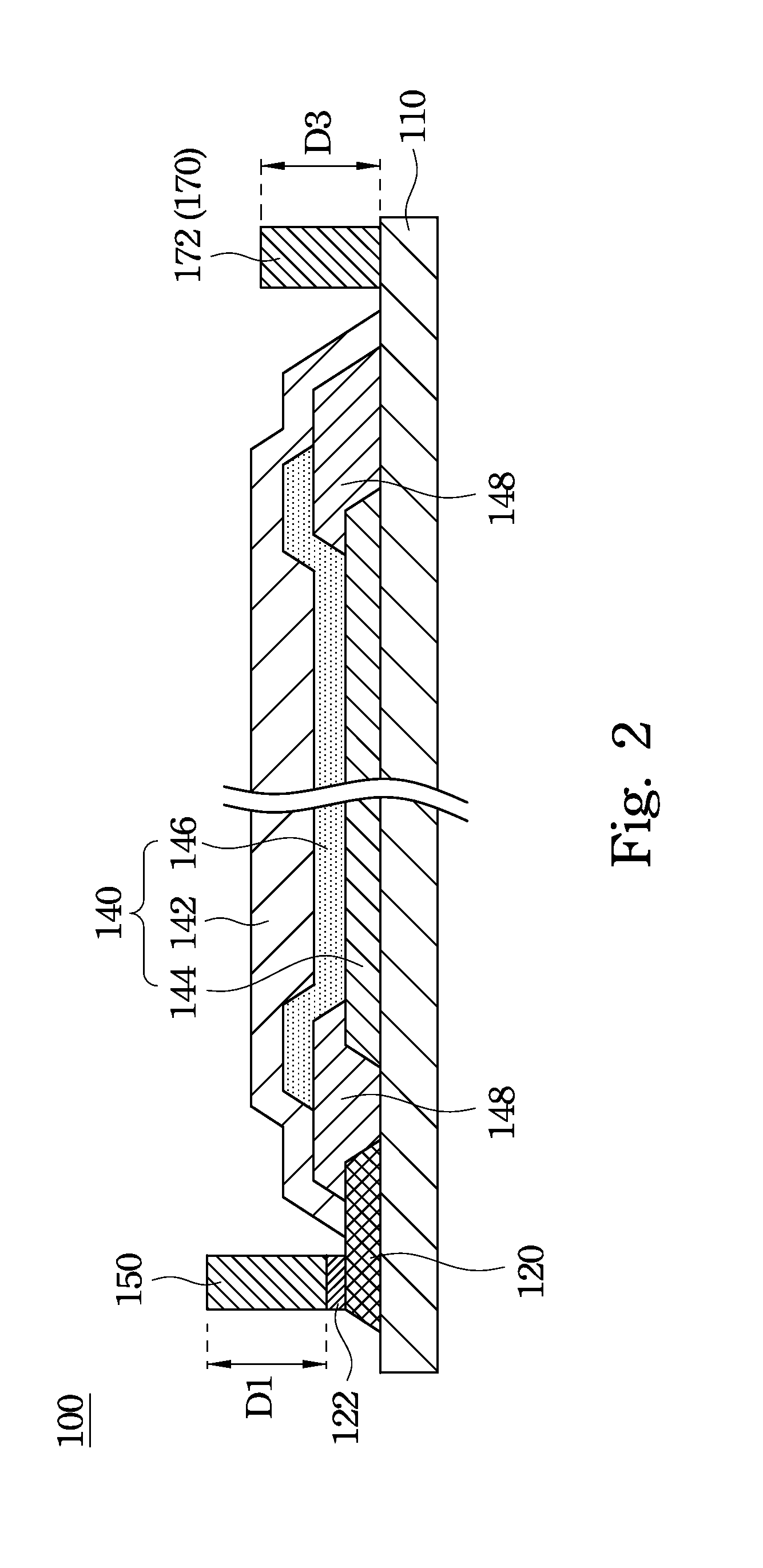
[0041]FIG. 1 is a top view of an organic light emitting diode module 100 according to an embodiment of the present invention. As shown in FIG. 1, the organic light emitting diode module 100 includes a substrate 110, a first electrode 120, a pair of second electrodes 130, a light emitting element 140, a first copper foil 150, a pair of second copper foils 160, and a cross connection conductor 170. The first and second electrodes 120, 130 and the light emitting element 140 are located on the substrate 110, and the second electrodes 130 are in an arrangement opposite to one another. T...


PUM


Abstract

An organic light emitting diode module is provided and includes a substrate, a first electrode located on the substrate, a pair of second electrodes located on the substrate, a light emitting element located on the substrate, a first copper foil electrically connected to the first electrode, a pair of second copper foils respectively electrically connected to the second electrodes, and a cross connection conductor electrically connected to the second copper foils. The second electrodes are in an arrangement opposite to one another. The light emitting element includes a first electrode layer electrically connected to the first electrode, a second electrode layer located between the second electrodes and electrically connected to the second electrodes, and an organic light emitting layer located between the first and second electrode layers.

Description

RELATED APPLICATIONS[0001]This application claims priority to Taiwan Application Serial Number 101129563, filed Aug. 15, 2012, which is herein incorporated by reference.BACKGROUND[0002]1. Technical Field[0003]The present disclosure relates to a light emitting device, and more particularly to an organic light emitting diode module.[0004]2. Description of Related Art[0005]An organic light emitting diode (OLED) includes an anode conductive layer, an organic light emitting layer, and a cathode conductive layer. Generally, the anode conductive layer is indium tin oxide (ITO), and the cathode conductive layer is a metal sheet. The organic light emitting layer is located between the anode and cathode conductive layers, such that the organic light emitting diode has a layered structure with the organic light emitting layer sandwiched between the anode and cathode conductive layers. When power is provided to the anode and cathode conductive layers, the organic light emitting layer can emit l...

Claims


Application Information

Patent Timeline
Patent Type & Authority Patents(United States)
IPC IPC(8): H01L51/00H01L27/32H01J1/62H01L51/52
CPCH01L27/32H01L51/5203H10K50/805H10K59/00
Inventor LIN, CHEN-CHIHUNG, CHIH-YI
Owner OPTRONIC SCI LLC
Why Eureka
Try Eureka