
System and method for implanting spinal stabilization devices

a spinal stabilization device and system technology, applied in the field of system and method for implanting spinal stabilization devices, can solve the problems of prolonged recovery time, increased risk of infection, and increased so as to reduce the risk of iatrogenic injuries to vital structures, improve visualization, and reduce the effect of technical difficulty of these operations

Inactive Publication Date: 2011-01-25
KIC VENTURES LLC
View PDF10 Cites 17 Cited by
  • Summary
  • Abstract
  • Description
  • Claims
  • Application Information

AI Technical Summary

Benefits of technology

This approach reduces tissue trauma, shortens recovery time, decreases hospitalization costs, and enhances surgical precision by allowing for the placement of stabilization devices through minimally invasive techniques without the need for open surgery, improving visualization and reducing iatrogenic injuries.

Problems solved by technology

These procedures result in extensive tissue traumatization and consequently in prolonged recovery time, risk of infections, high hospitalization costs, pain that can be more severe than the pain due to the initial ailment, and in some cases permanent scarring.
The potential for the avoidance of general anesthesia reduces post-operative recovery time and the risk of complications.
Minimally invasive surgical procedures are especially desirable for spine surgeries because spine pathologies are located deep within the body without clear muscle planes and there is danger of damaging the adjacent neural and vascular tissues.
The destruction to the spinal structures is even more extensive during the spine stabilization procedures, which require more lateral tissue dissection and exposure to access the transverse processes and pedicles for placement of pedicle screws, rod constructs for stability, and bone graft under direct vision.
Placement of these connecting elements requires open surgery, which is currently one of the major limitations of other percutaneous access methodologies.
The emerging percutaneous access systems that address some of the limitations of open surgeries are limited to cylindrical tubes, cannulas, or blades.
One of the shared limitations of these systems is that they all have solid walls which in our experience tend to reduce visualization of the deep structures and require specific alignment of a predefined access slot.

Method used


Image

  • System and method for implanting spinal stabilization devices
  • System and method for implanting spinal stabilization devices
  • System and method for implanting spinal stabilization devices

Examples


Embodiment Construction

[0046]The present invention relates to a system and a method for placing spinal stabilization devices into a patient's back via minimally invasive surgery (MIS).

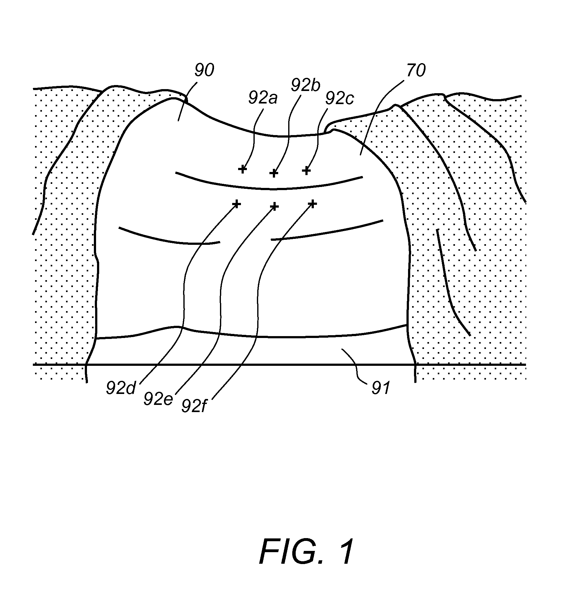
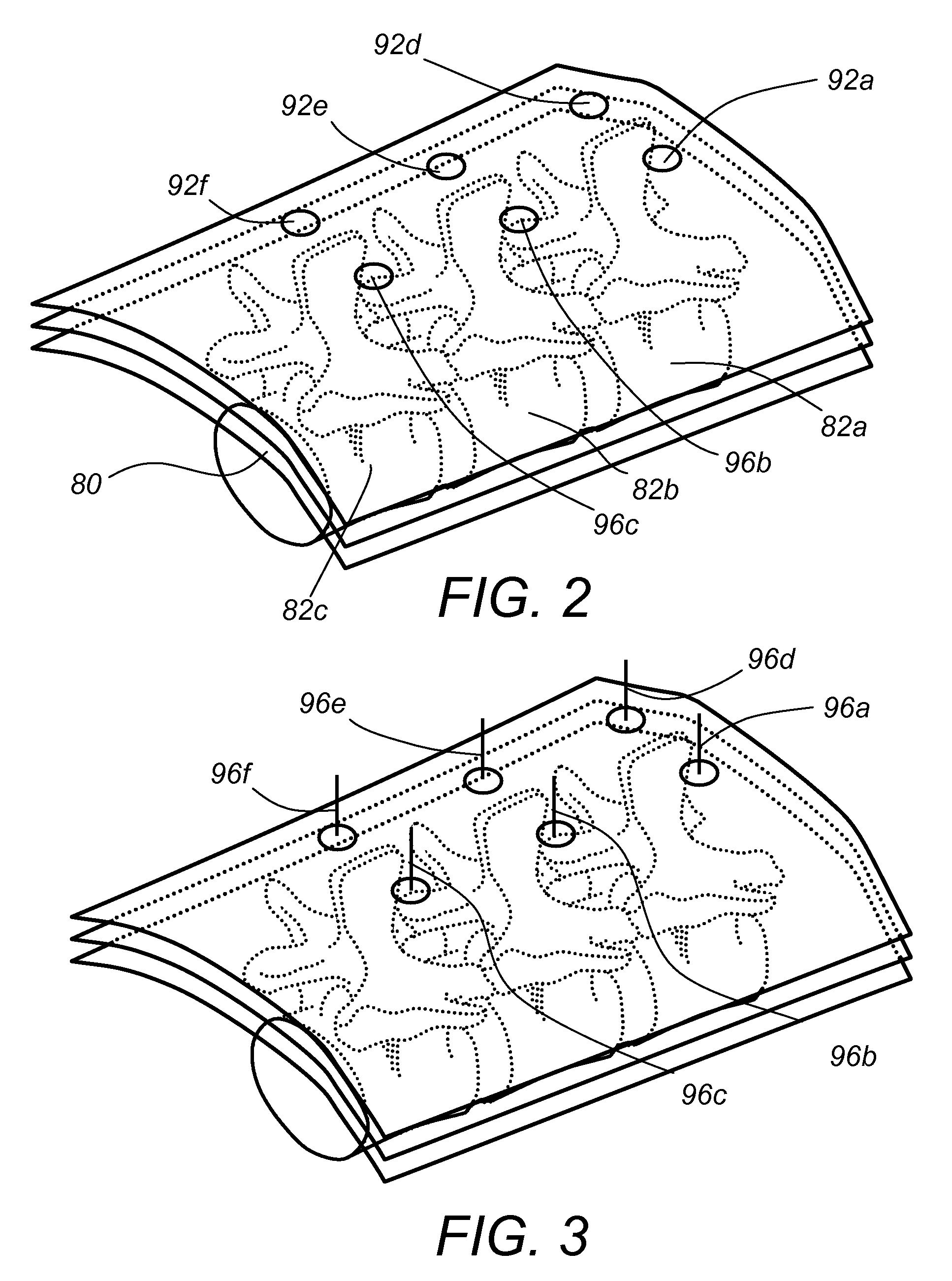
[0047]Referring to FIG. 1, a patient 90 is positioned prone, lying flat on an operating table 91 in preparation for a minimally invasive surgery. Locations 92a-92f are marked on the patient's lower back corresponding to underlying pedicle locations of adjacent vertebrae 82a, 82b, 82c, respectively, and incisions are made on the marked areas, as shown in FIG. 2. The incisions extend through the lumbodorsal fascia to the deep tissues. Next, guide K-wires 96a-96f are inserted through the openings formed by the incisions and are placed in contact with the underlying pedicles, as shown in FIG. 3. For MIS procedures the tissue around the K-wires is dilated and access devices are inserted around the locations of the K-wires leading to the underlying pedicles, shown in FIG. 4. For spinal stabilization procedures, pedicle screws are ...


PUM


Abstract

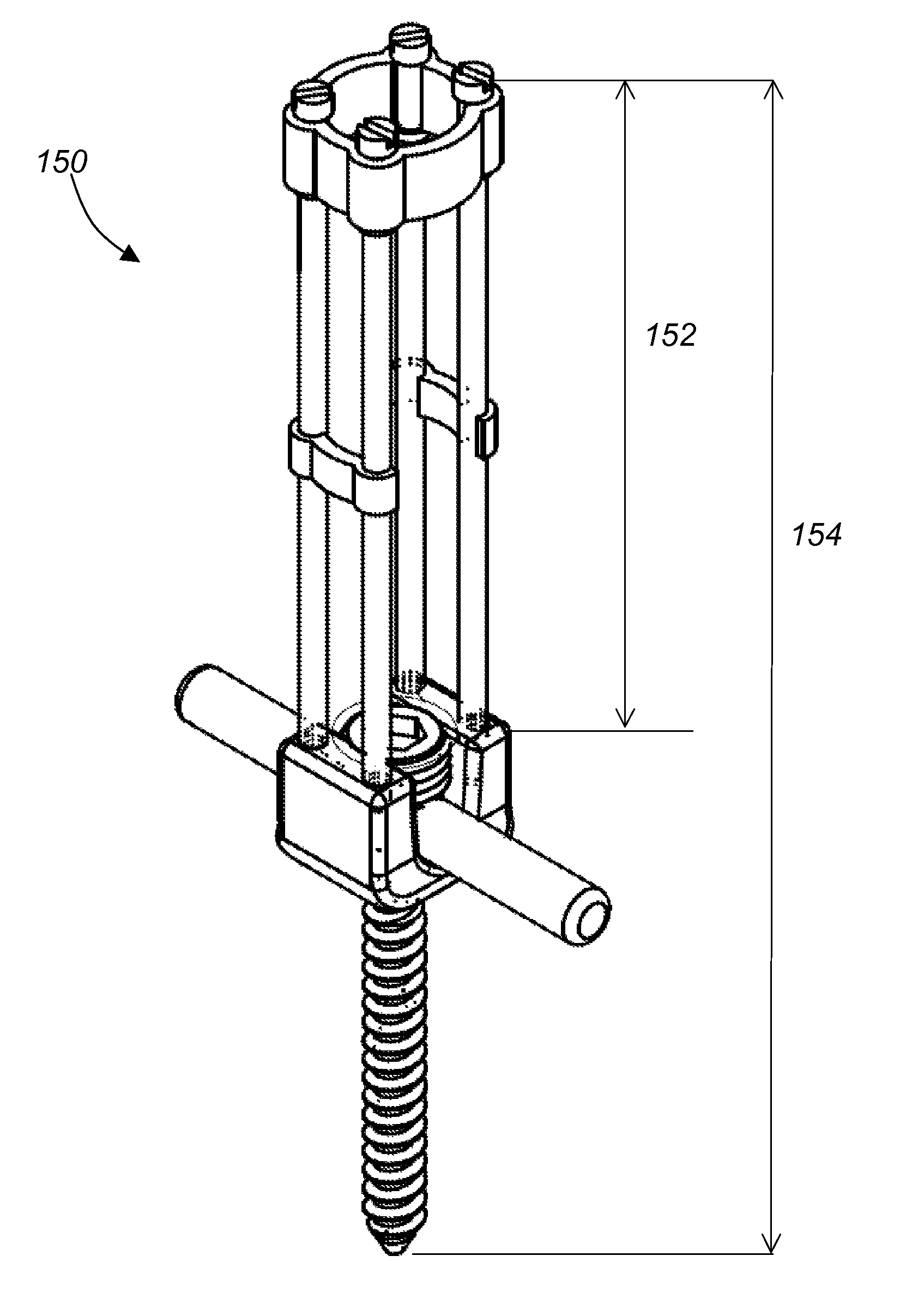
A system and a method for providing minimally invasive access to the spine of a patient and implanting spinal stabilization devices. The system utilizes one or more post-type access devices. The post-type access device includes a cage with an aperture and two or more posts extending from the cage and being removably attached to the cage. The posts are supported at the top of the access device by a support ring structure. A pedicle screw is inserted into the access device and through the cage aperture and the screw-access device assembly is inserted into an opening of the patient's body. The base aperture is dimensioned to securely support the head of the screw. Side openings between the posts allow the insertion and placement of stabilization devices, such as rods, wires, or plates from almost any direction.

Description

CROSS REFERENCE TO RELATED CO-PENDING APPLICATIONS[0001]This application is a continuation in part of U.S. application Ser. No. 10 / 669,927 filed on Sep. 24, 2003 and entitled APPARATUS AND METHOD FOR CONNECTING SPINAL VERTEBRAE the contents of which are expressly incorporated herein by reference. This application also claims the benefit of U.S. provisional application Ser. No. 60 / 737,666 filed on Nov. 17, 2005 and entitled “SYSTEM AND METHOD FOR IMPLANTING SPINAL STABILIZATION DEVICES”, the contents of which are expressly incorporated herein by reference.FIELD OF THE INVENTION[0002]The present invention relates to a system and a method for implanting spinal stabilization devices, and more particularly to a system and a method that allow the percutaneous transfer of connecting devices and instruments within one access channel or between two or more adjacent access channels placed deep in two or more locations of the patient's body, respectively.BACKGROUND OF THE INVENTION[0003]It is ...

Claims


Application Information

Patent Timeline
Patent Type & Authority Patents(United States)
IPC IPC(8): A61B17/70
CPCA61B17/7037A61B17/7085A61B17/7091A61B17/7032A61B17/7049A61B17/8605A61B17/8685A61B17/56A61B17/60
Inventor CHIN, KINGSLEY RICHARDIBARRA, MATTHEW
Owner KIC VENTURES LLC
Learn More