Thin film tube reactor with rotating reservoir

a thin film tube reactor and reservoir technology, applied in the direction of thin film liquid chemical reaction, gas-gas reaction process, liquid chemical process, etc., can solve the problems of rapid temperature change, difficult to achieve, and inability to achieve proper hydrodynamics, etc., to achieve the effect of minimizing turbulen

Inactive Publication Date: 2011-01-25
CLARKSON UNIVERSITY
View PDF2 Cites 9 Cited by
  • Summary
  • Abstract
  • Description
  • Claims
  • Application Information

AI Technical Summary

Benefits of technology

[0011]The present invention provides for a method and apparatus directed to a tube reactor having a substantially tubular body portion that includes a conical section, an entry port, an opposing exit port, and an axis extending between the ports through the body portion. The tubular body portion can rotate about the axis. The conical section can be positioned within the tubular body portion near the entry port. At least one reactant can be fed into the tubular body portion, and directed toward the conical section. An inner surface of the tubular body portion receives the reactants from the conical section, and processes the reactants while the tubular body portion is rotating. An insert may be positioned within the t

Problems solved by technology

A common problem in chemical reaction processes is how to achieve the proper hydrodynamics in the reactor to efficiently produce the desired products.
In some cases rapid temperature changes are desired though difficult to achieve due to the thermal inertia of the reaction components.
Also, it is often difficult to ensure proper saturation of the reaction components by an electromagnetic field as the outermost portion of the mixture of reacta

Method used


Image

  • Thin film tube reactor with rotating reservoir
  • Thin film tube reactor with rotating reservoir
  • Thin film tube reactor with rotating reservoir

Examples


Embodiment Construction

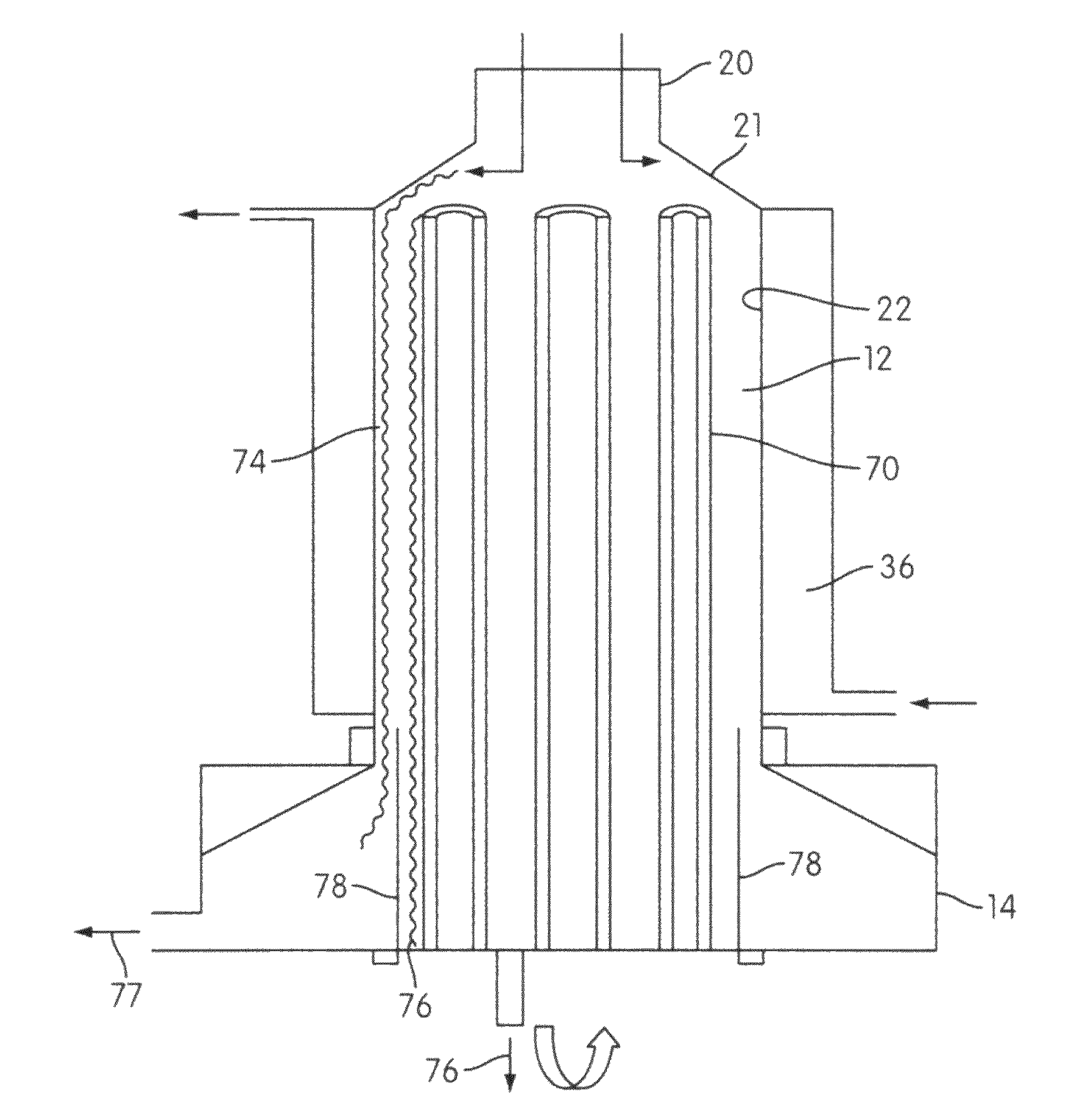
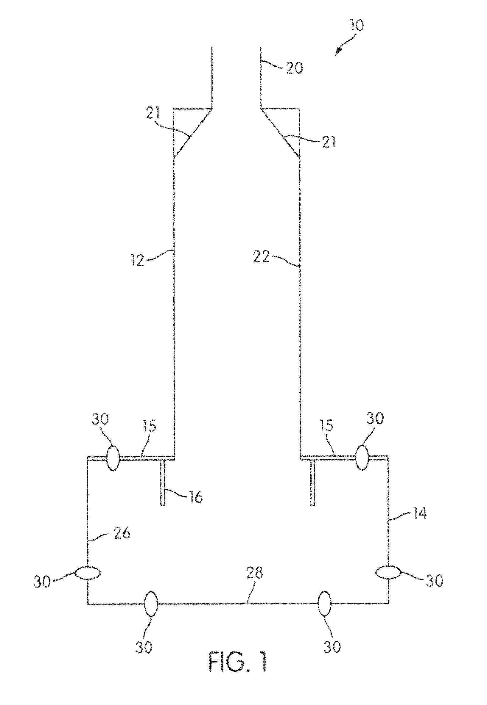
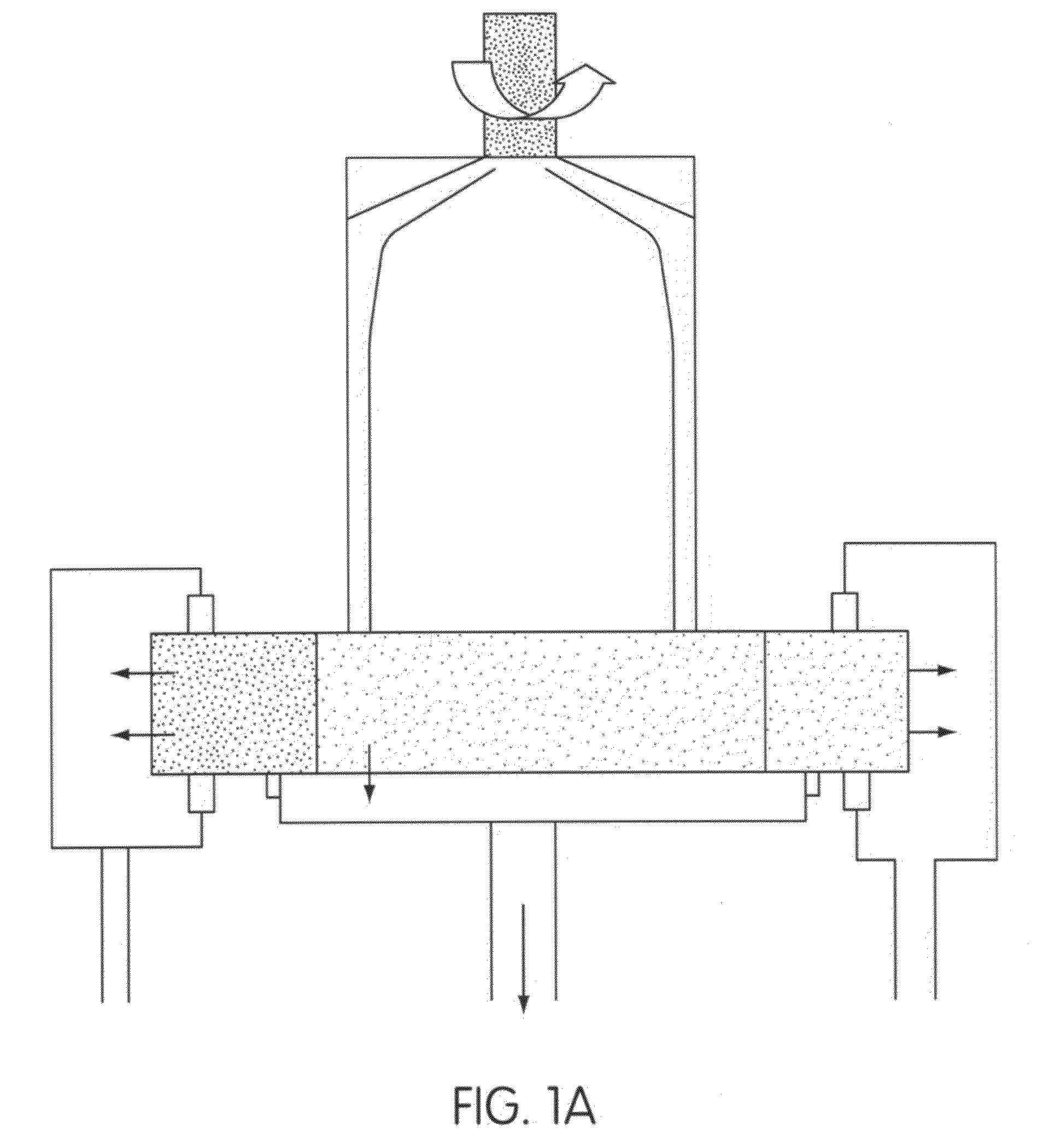
[0025]Referring to FIGS. 1 and 1A, there is shown the thin film tube reactor of the present invention. The tube reactor 10 includes a primary tube 12 having a substantially tubular body portion that can rotate about an axis extending from one end of the tubular body to an opposite end, so as to generate a centrifugal force. The tube reactor 10 also includes a conical section 21 positioned in the primary tube 12, and a separation reservoir 14 capable of rotating. In some embodiments described below, the tube reactor can also include a variety of components, such as, inserts that can be utilized to provide the tube reactor 10 with additional processing options. The tube reactor 10 can be utilized to provide enhanced control in a particular reaction, and to extend the residence time for the reaction. The tube reactor 10 can also be adapted to perform interfacial chemistry. Specifically, interaction between fluids with different densities.

[0026]The primary tube 12, which is rotatable ab...


PUM


Abstract

A tube reactor having a substantially tubular body portion including a conical section, an entry port, an opposing exit port, and an axis extending between the ports through the body portion. The tubular body portion being rotatable about the axis. At least one reactant can be fed into the tubular body portion and directed toward the conical section. An inner surface of the tubular body portion receives the reactants from the conical section, and processes the reactants. An insert may be positioned within the tubular body portion to further process the reactants along the inner surface. A rotating reservoir having a damper can be coupled to the rotating tubular body portion. The damper receives the processed reactants from the inner surface of the tubular body portion, and guides the processed reactants into the rotating reservoir to minimize turbulence. The rotating reservoir then separates the processed reactants by density.

Description

FIELD OF THE INVENTION[0001]This invention relates to chemical reactors and thermal processing equipment.BACKGROUND[0002]A common problem in chemical reaction processes is how to achieve the proper hydrodynamics in the reactor to efficiently produce the desired products. The reactants need to be mixed so that the molecules of the reaction components come into contact with the other components in the reaction including catalysts. The presence of a gaseous reactant requires the increase of the surface area of the boundary between the gas and the liquid components to increase the efficiency of the reaction. Many processes require fine temperature control or added energy from an electromagnetic field. In some cases rapid temperature changes are desired though difficult to achieve due to the thermal inertia of the reaction components. Also, it is often difficult to ensure proper saturation of the reaction components by an electromagnetic field as the outermost portion of the mixture of r...

Claims


Application Information

Patent Timeline
IPC IPC(8): B01J19/28
CPCB01J10/007B01J10/02B01J19/121B01J19/123B01J19/126B01J19/1887B01J19/28B01J19/006B01D61/025B01D61/027B01D61/145B01D61/147B01J2219/00094B01J2219/00081
Inventor JACHUCK, ROSHAN
Owner CLARKSON UNIVERSITY
Why Eureka
Try Eureka