Ultrasonic transducer which is either crimped or welded during assembly

a transducer and crimping technology, applied in the field of ultrasonic transducers, can solve the problems of reducing the output power of the product, affecting the work efficiency of the installation of piezoelectric elements with an adequate holding force, and affecting the performance of the installation of the piezoelectric elements, so as to achieve the effect of preventing the dispersion of vibration characteristics and increasing the output power

Inactive Publication Date: 2011-01-25
NGK SPARK PLUG CO LTD
View PDF11 Cites 316 Cited by
  • Summary
  • Abstract
  • Description
  • Claims
  • Application Information

AI Technical Summary

Benefits of technology

[0007]The invention has been conducted in order to solve the problems. It is an object of the invention to provide an ultrasonic transducer in which application of torsional stress and the like to piezoelectric elements can be suppressed, the vibration characteristics can be prevented from being dispersed, and miniaturization and increase of the output power are enabled, and also a method of producing such an ultrasonic transducer.
[0018]According to the second aspect of the invention, it is possible to provide an ultrasonic transducer in which generation of torsional stress and the like that may be applied to piezoelectric elements can be suppressed, the vibration characteristics can be prevented from being dispersed, and miniaturization and increase of the output power are enabled, and also a method of producing such an ultrasonic transducer.

Problems solved by technology

Namely, the fixation by screwing restricts the size of the piezoelectric elements or the product body, and, therefore, causes miniaturization of the product, the increase of the output power of the product by applying large-diameter piezoelectric elements, and the like, to be impeded.
In an ultrasonic transducer having a structure which is assembled by fastening a screw to a piezoelectric element side as in Japanese Patent No. 3,914,050 and JP-A-2004-160081, however, the friction force generated during the work of fastening the screw acts as an cause of impeding the work, so that the work of installing the piezoelectric elements with an adequate holding (clamping) force is relatively difficult to perform.
In the ultrasonic transducer having the structure in which a screw is fastened to a piezoelectric element side, moreover, there is a possibility that, due to torsional stress acting on the piezoelectric elements or the like, the positions of the piezoelectric elements are deviated from predetermined designed positions, thereby causing the vibration characteristics of the ultrasonic transducer to be dispersed.
Furthermore, there are fears such as that, because of the above-mentioned stress in the torsional direction, mechanical stress which is larger than an allowable level is applied to the piezoelectric elements.

Method used


Image

  • Ultrasonic transducer which is either crimped or welded during assembly
  • Ultrasonic transducer which is either crimped or welded during assembly
  • Ultrasonic transducer which is either crimped or welded during assembly

Examples


first and second embodiments

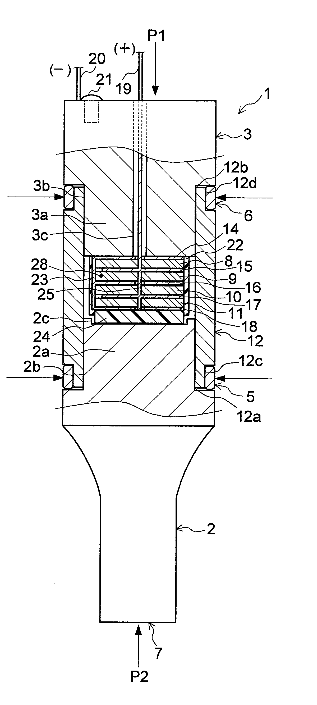
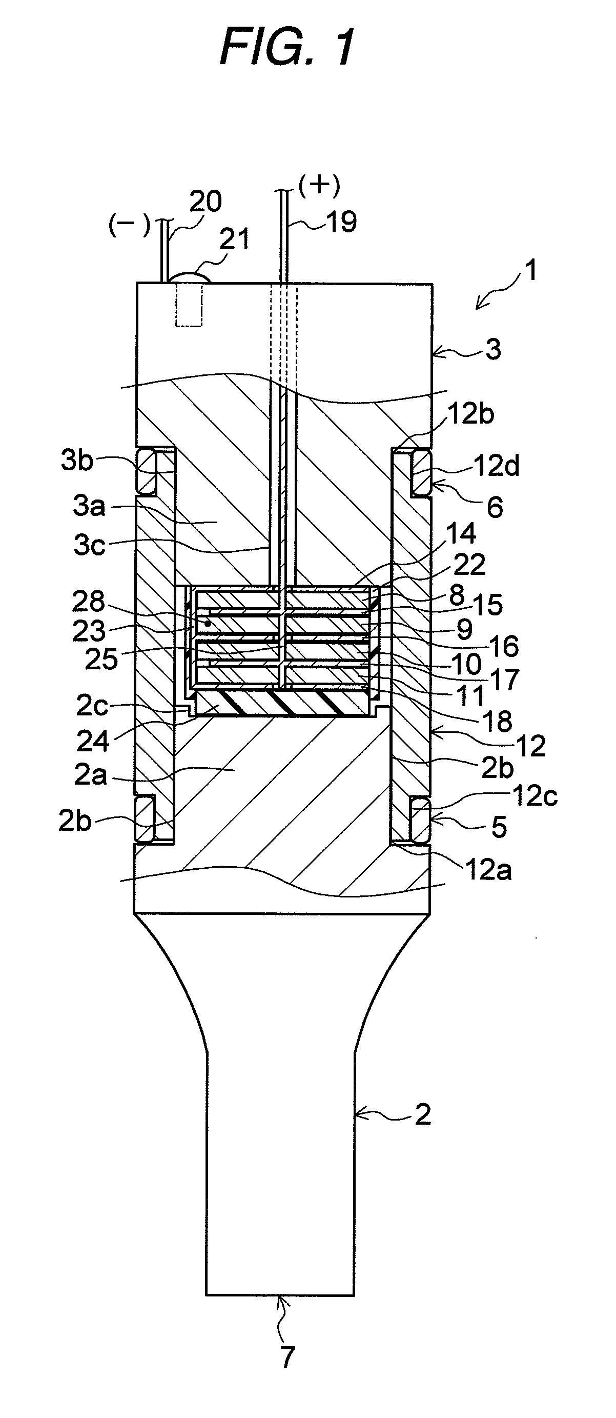
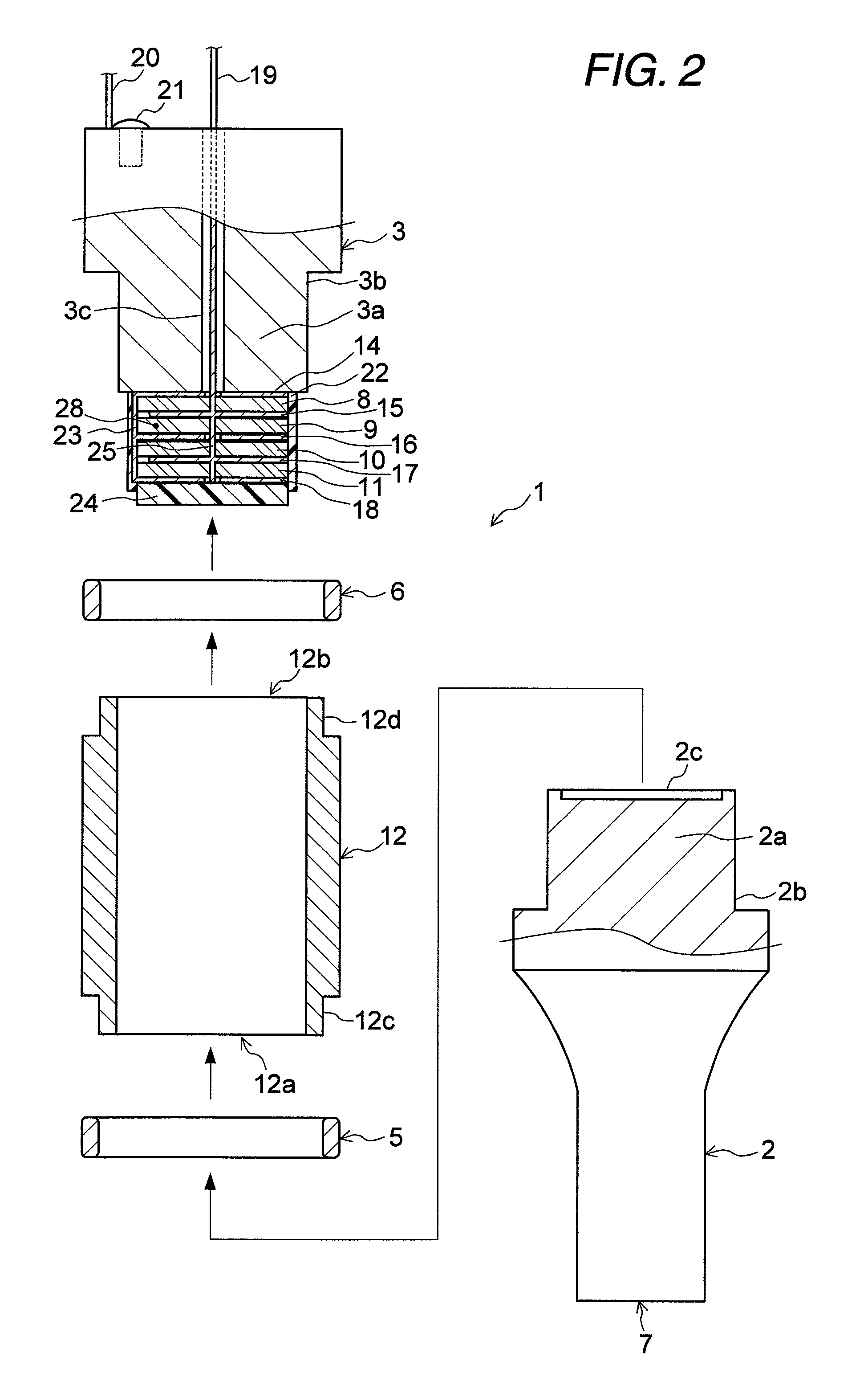
[0046]FIG. 1 is a front view showing in partially section an ultrasonic transducer 1 of a first embodiment of the invention, and FIG. 2 is an exploded view showing partial components of the ultrasonic transducer 1. FIG. 3 is a view illustrating a method of producing the ultrasonic transducer 1.

[0047]FIG. 17 is a front view showing in partially section an ultrasonic transducer 1′ of a second embodiment of the invention, and FIG. 18 is an exploded view showing partial components of the ultrasonic transducer 1′. FIG. 19 is a view illustrating a method of producing the ultrasonic transducer 1′.

[0048]The ultrasonic transducers 1, 1′ of the first and second embodiments are used as a driving source of a handheld ultrasonic device such as an ultrasonic cutter or an ultrasonic dental scaler. As shown in FIGS. 1 and 2, and 17 and 18, the ultrasonic transducers 1, 1′ are formed into a columnar shape having, for example, a total length of 21.9 mm and a maximum outer diameter of 4.0 mm, and main...

third embodiment

[0073]Next, a third embodiment of the invention will be described with reference to FIG. 4. FIG. 4 is a front view showing in partially section an ultrasonic transducer 31 of the embodiment. In FIG. 4, components which are identical with those of the ultrasonic transducer 1 of the first embodiment shown in FIGS. 1 to 3 are denoted by the same reference numerals, and their description is omitted.

[0074]As shown in FIG. 4, the ultrasonic transducer 31 of the embodiment includes a front plate 32, a back plate 33, and a side plate 34 in place of the front plate 2, back plate 3, and side plate 12 which are disposed in the ultrasonic transducer 1 of the first embodiment, and each of the front plate 32 and the back plate 33 is crimped to the side plate 34 without using a crimp ring. Namely, a metal material which is relatively soft so as to be easily plastically deformed in a crimping process, such as duralumine or soft iron is used as a material constituting the front plate 32, the back pl...

fourth embodiment

[0078]Next, a fourth embodiment of the invention will be described with reference to FIG. 5. FIG. 5 is a front view showing in partially section an ultrasonic transducer 41 of the embodiment. In FIG. 5, components which are identical with those of the ultrasonic transducer 1 of the first embodiment shown in FIGS. 1 to 3 are denoted by the same reference numerals, and their description is omitted.

[0079]In the ultrasonic transducer 41 of the embodiment, as shown in FIG. 5, the crimp ring 5 which is disposed in the ultrasonic transducer 1 of the first embodiment is omitted, and a front plate 42 having a cover portion 42a is provided in place of the front plate 2 and the side plate 12. Namely, the front plate 42 is realized by configuring the front plate 2 and the side plate 12 in the first embodiment by a single member.

[0080]In the ultrasonic transducer 41, in a state where the piezoelectric element unit 28 is pressed by an adequate load through the front plate 42 and the back plate 3,...


PUM


Abstract

An ultrasonic transducer includes: piezoelectric elements; a pair of clamping members which clamp said piezoelectric elements; and a cover member which is crimped to at least one of said pair of clamping members in a state where said cover member cooperates with said pair of clamping members to surround said piezoelectric elements.

Description

FIELD OF THE INVENTION[0001]The present invention relates to an ultrasonic transducer which generates ultrasonic vibration by electrical distortion of piezoelectric elements, and a method of producing such a transducer.BACKGROUND OF THE INVENTION[0002]A Langevin type ultrasonic transducer having a configuration in which a stack unit of piezoelectric elements that are integrally sintered is fitted into a recess formed in a metal-made vibration block has been proposed (for example, see Japanese Patent No. 3,914,050).[0003]In the ultrasonic transducer disclosed in Japanese Patent No. 3,914,050, a screw hole (female thread) is formed in the inner wall of the recess of the vibration block, and a bolt is fastened to the screw hole, whereby the stack unit of piezoelectric elements is fixed to the vibration block.[0004]Furthermore, a handpiece for surgical operation incorporating an ultrasonic transducer having a structure in which, for example, a stack type piezoelectric member housed in a...

Claims


Application Information

Patent Timeline
Patent Type & Authority Patents(United States)
IPC IPC(8): H01L41/04H01L41/08
CPCA61B17/320068B06B1/0607G10K11/004A61B2017/320089
Inventor TAKI, HIDEAKIKIMURA, WATARUYOSHIDA, NORITAKASATO, NAOHITOONODA, MITSUGUKAWAJI, HIROYUKI
Owner NGK SPARK PLUG CO LTD
Why Eureka
Try Eureka