Reflected wave clock synchronization

a technology of reflected wave and clock, which is applied in the direction of instruments, measurement devices, and antennas, can solve the problems of many vacuum tubes of radar systems giving rise to frequent failures, tube failures, and reliability problems,

Inactive Publication Date: 2011-01-25
LOCKHEED MARTIN CORP
View PDF49 Cites 52 Cited by
  • Summary
  • Abstract
  • Description
  • Claims
  • Application Information

AI Technical Summary

Problems solved by technology

Early radar systems used vacuum tubes in analog circuits, and were subject to reliability problems.
When left in operation, the many vacuum tubes of a radar system would give rise to frequent failures attributable to normal aging and often excessive heat.
If turned off when not in use, the thermal cycling would often result in tube failures at each turn-on, requiring trouble-shooting and maintenance.
Solid-state devices have been limited, however, in their ability to handle the large amounts of power required for radar transmissions.
The design of radar systems involves a complex tradeoff among many factors, among which are system complexity, cost, weight, performance, and reliability.
The problems associated with radar system design are more numerous and complex than might be thought.
Among other problems associated with radar system design are that the beamformers, circulators (if any), T / R modules, and filters (if any) associated with each elemental antenna of the antenna array tend to be physically large.
The large size of the T / R modules tends to make selection of an appropriate inter-antenna-element spacing difficult.
These analog modulation devices and analog beamformers are expensive, require considerable space, and must be cooled.

Method used


Image

  • Reflected wave clock synchronization
  • Reflected wave clock synchronization
  • Reflected wave clock synchronization

Examples


Embodiment Construction

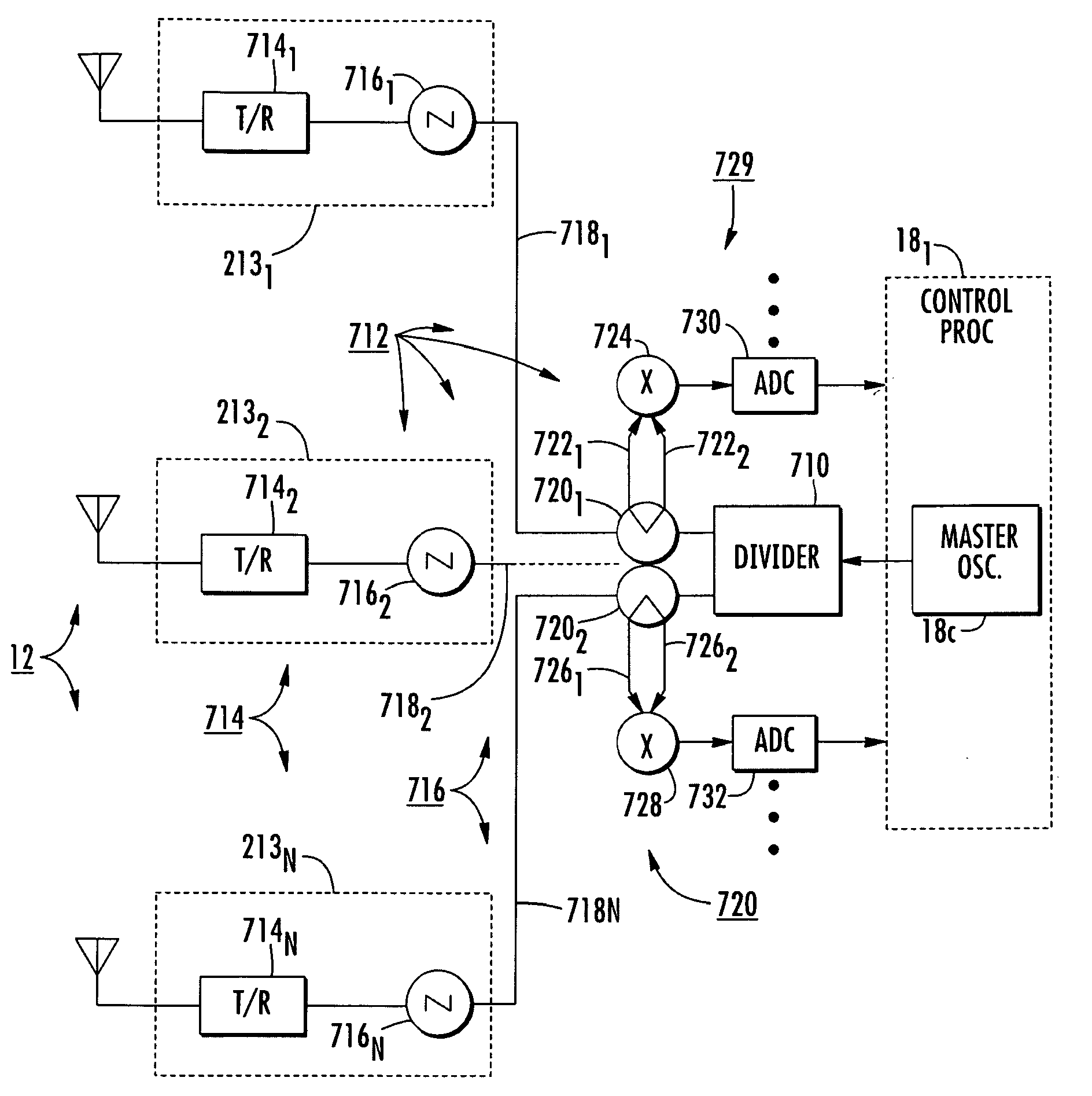
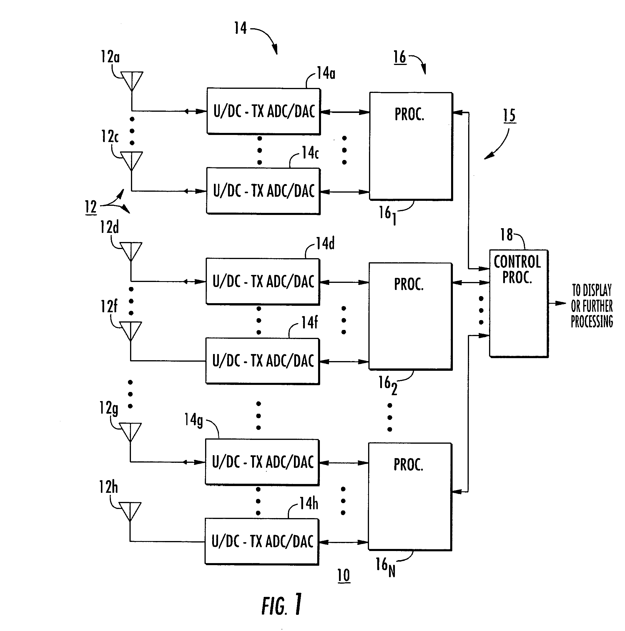
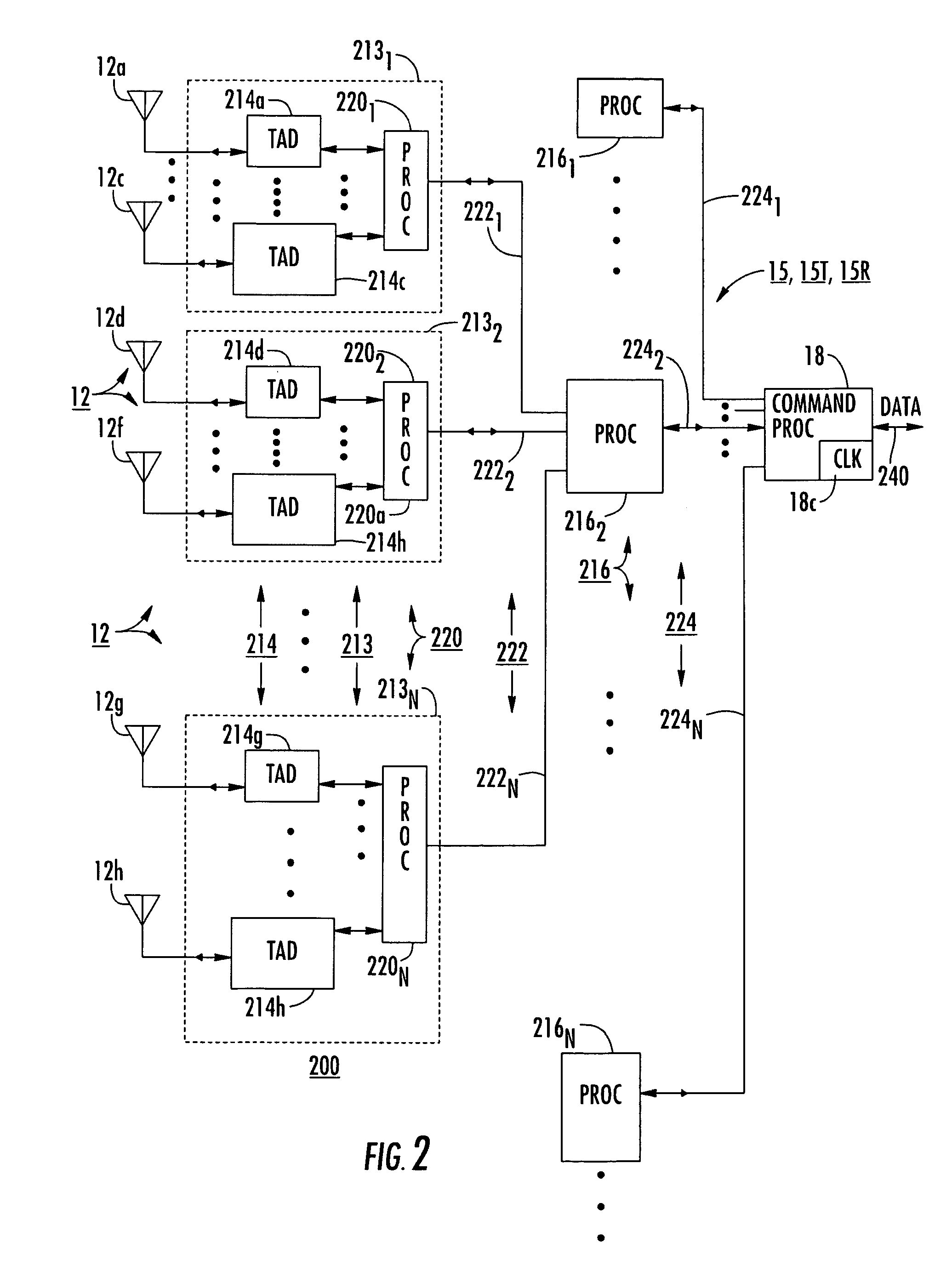
[0043]In the arrangement of FIG. 2, as mentioned, the processors 2201, 2202, . . . 220N of set 220 of processors of FIG. 2 interface between their associated transceiver / ADC / DAC arrangements (TADs) of set 214 and buses or network digital paths 2221, 2222, . . . , 222N of set 222 of serial buses. In both transmit and receive modes of operation of the arrangement of FIG. 2, command processor 18 of generalized processor 15 transmits clock data, together with other information, through the processing and distribution network 15 (including transmit portions 15T and receive portions 15R). As illustrated in FIG. 6, each processor 2201, 2202, . . . , 220N of set 220 of processors can may include a local oscillator (LO) which generates the clock signals for its associated transceiver / ADC / DAC (TADs) of set 214 of TADs. More particularly, in the arrangement of FIG. 6, processors 2201, 2202, . . . , 220N of set 220 of processors each include a local oscillator (LO), namely 6201, 6202, . . . , 6...


PUM


Abstract

A radar system has a phased-array antenna and plural local oscillators for controlling local transmit / receive units. The local oscillators are slaved to a master oscillator. The analog clock signal paths are subject to relative changes in electrical length. The electrical lengths of the signal paths are measured by phase-detecting forward- and reverse-direction clock signal flows. The phase-detected information for each signal path is a measure of the time delay. The radar command processor receives the measure of time delay and corrects the radar operation in response thereto.

Description

BACKGROUND OF THE INVENTION[0001]Radar systems are widely known. Early radar systems used vacuum tubes in analog circuits, and were subject to reliability problems. In particular, the vacuum tubes would age with time, and the operating parameters of the radar system would vary on an almost continuous basis, requiring constant realignment. When left in operation, the many vacuum tubes of a radar system would give rise to frequent failures attributable to normal aging and often excessive heat. If turned off when not in use, the thermal cycling would often result in tube failures at each turn-on, requiring trouble-shooting and maintenance.[0002]With the advent of solid-state devices, some of the low-frequency, low-power functions of a radar system could be converted away from tubes. This often provided a major improvement in reliability. The introduction of integrated circuits gave impetus for their use in the low-frequency, low-power sections of a radar system, and also gave impetus t...

Claims


Application Information

Patent Timeline
Patent Type & Authority Patents(United States)
IPC IPC(8): G01S13/00G01S7/40H04B7/00
CPCG01S7/282G01S7/4008H01Q3/26G01S2013/0254
Inventor ADAMS, GREGORY F.
Owner LOCKHEED MARTIN CORP
Why Eureka
Try Eureka