Analyzer

an analyzer and optical filter technology, applied in the field of analyzers, can solve the problems of difficult and frequent switching of optical filters, complicated control of rotating plates, and high positioning accuracy of expensive motors, and achieve the effect of preventing the complication of controlling the switching of optical filters

Active Publication Date: 2011-01-25
SYSMEX CORP
View PDF11 Cites 2 Cited by
  • Summary
  • Abstract
  • Description
  • Claims
  • Application Information

AI Technical Summary

Benefits of technology

[0008]The present invention has been proposed in order to solve the aforementioned problem, and an object of the present invention is to provide an analyzer at a cost lower than a conventional one, capable of switching optical filters frequently in a short period and requiring no positioning of the optical filters while inhibiting control of switching the optical filters from complication.

Problems solved by technology

In the conventional analyzer, however, the rotating plate must be repeatedly rotated and stopped and hence the optical filters are disadvantageously difficult to be switched frequently in a short period.
When the optical filters are switched, the rotating plate must be repeatedly rotated and stopped, which disadvantageously complicates control of the rotating plate.
The optical filter must be correctly stopped on the path of the light from the light source, and hence an expensive motor having a high positioning accuracy must be employed and positioning of the optical filter with respect to the path of the light from the light source is required.

Method used


Image

  • Analyzer
  • Analyzer
  • Analyzer

Examples


first embodiment

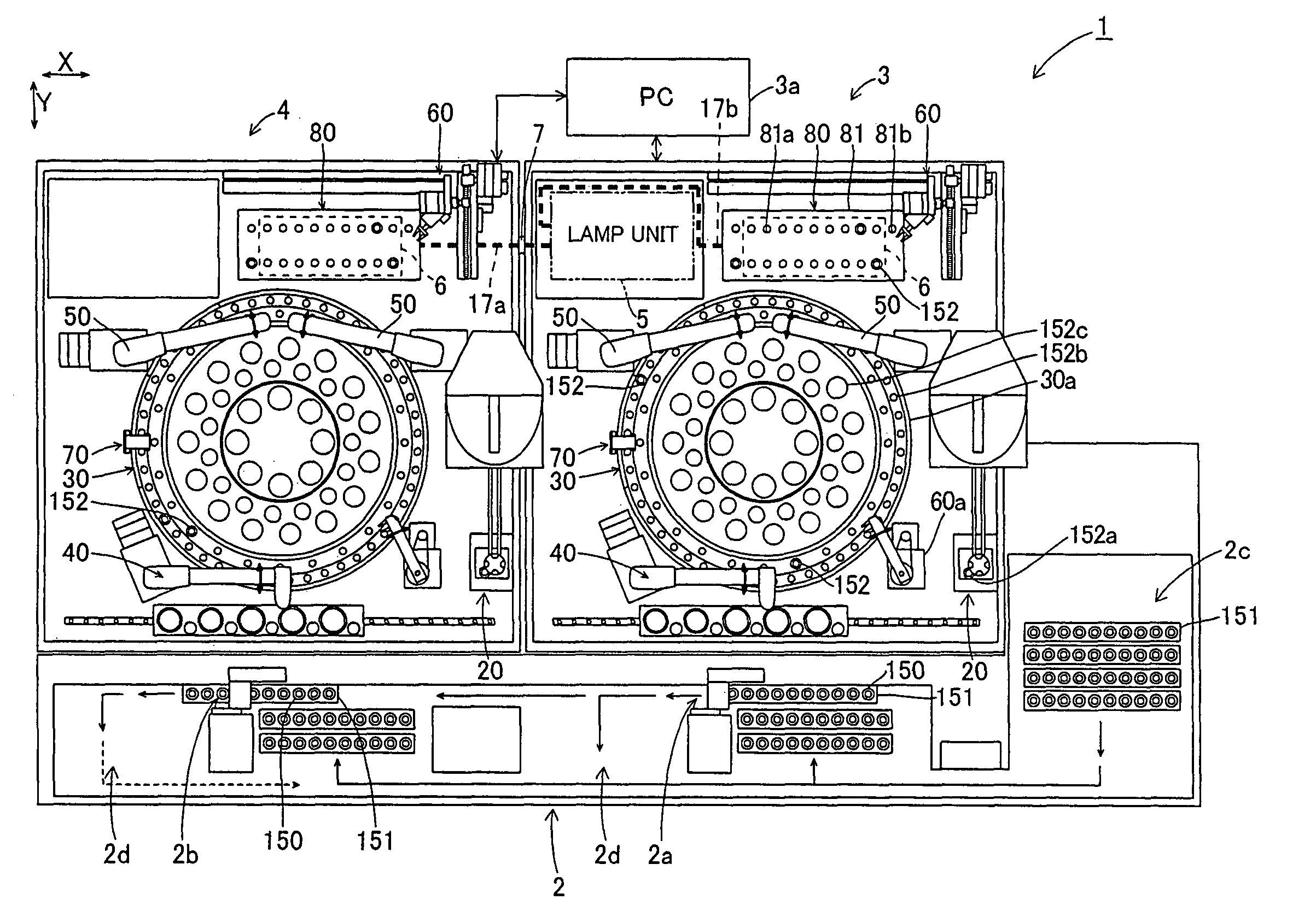
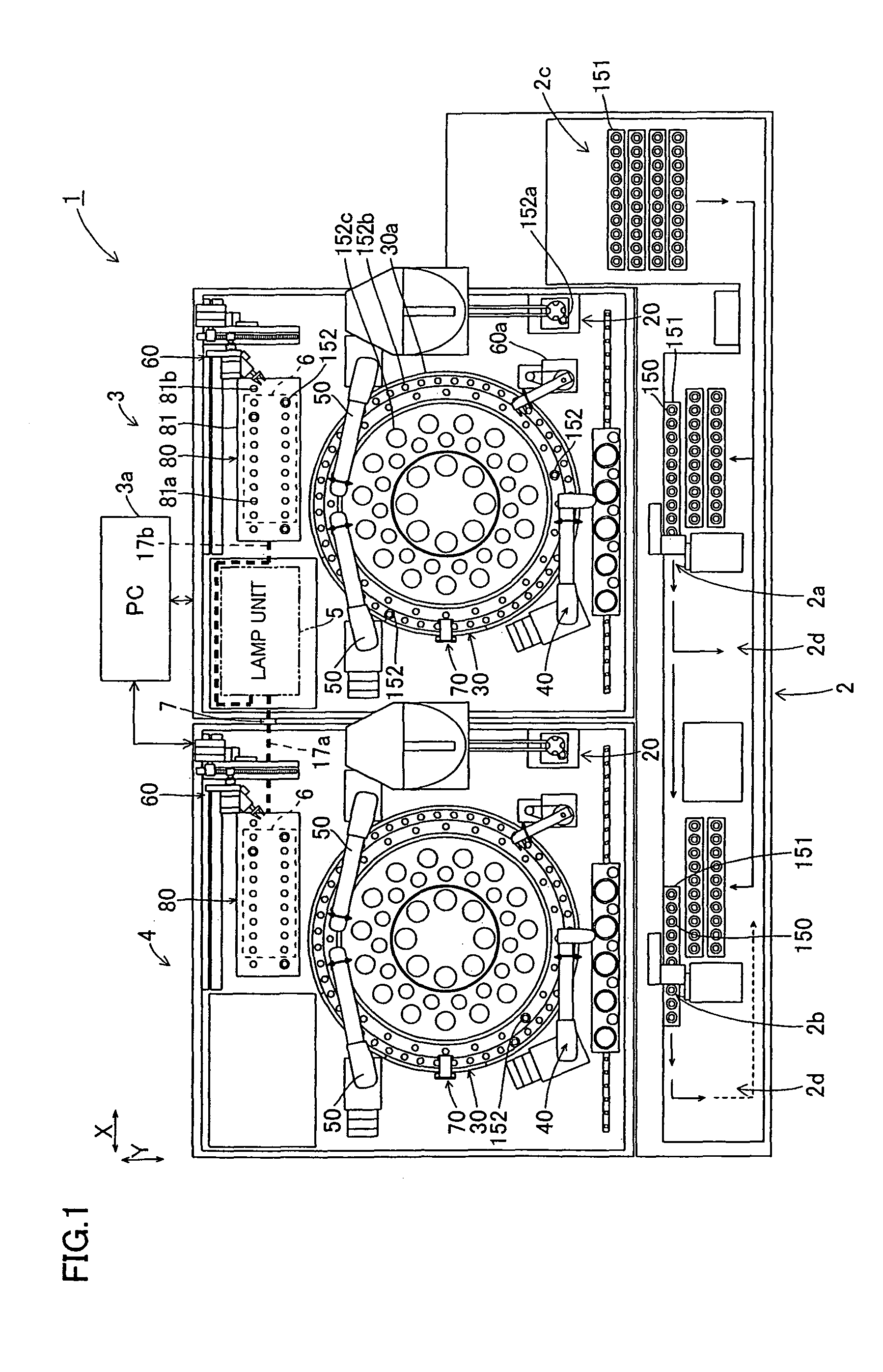
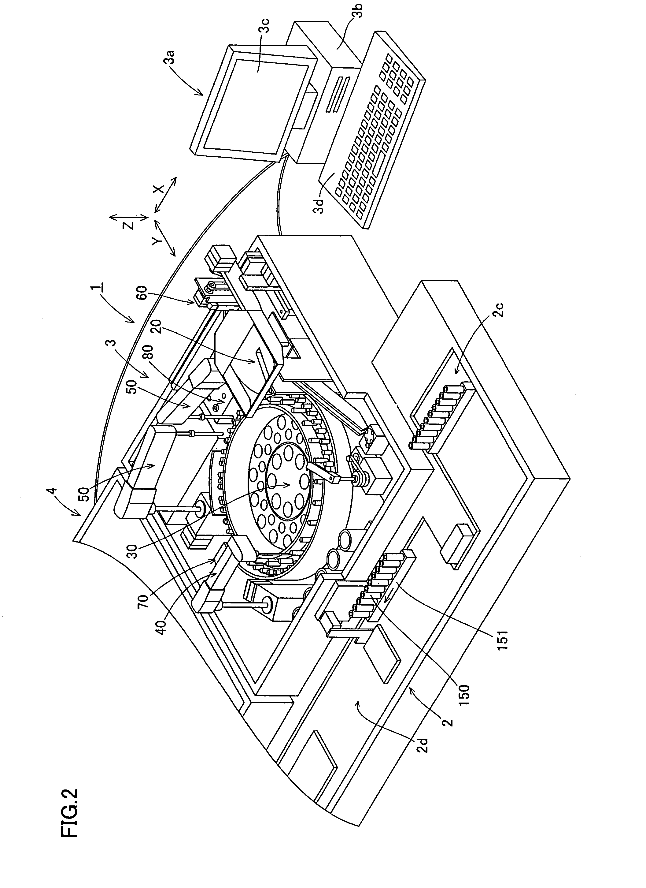
[0043]The structure of an analytic system 1 according to a first embodiment of the present invention is described with reference to FIGS. 1 to 12.

[0044]The analytic system 1 according to the first embodiment of the present invention is a system for optically measuring and analyzing the quantities and the degrees of activity of specific substances related to a blood coagulative / fibrinolytic function, employing blood plasma as a specimen. The analytic system 1 according to the first embodiment optically measures the specimen with a coagulation time method. The coagulation time method employed in the first embodiment is a measuring method detecting the process of coagulation of the specimen as change of transmitted light.

[0045]The structure of the analytic system 1 can be varied with the scale of an institution where the system 1 is installed. When installed in an institution having a relatively small number of specimens, for example, the analytic system 1 is constituted of an analyzer...

second embodiment

[0156]An operation of an analytic system according to a second embodiment of the present invention is now described. The analytic system according to the second embodiment are similar in structure to that of the analytic system 1 according to the aforementioned first embodiment, and hence redundant description thereof is omitted. In the analytic system according to the second embodiment, a control section 112 acquires data not with a differential signal of a reference signal but with detection signals of slits of the filter section 14 dissimilarly to the analytic system 1 according to the aforementioned first embodiment.

[0157]Initialization of the analytic system according to the second embodiment is described. The analytic system according to the second embodiment calculates a clock number p of a lapse from slit detection to start of data acquisition as described below. FIG. 26 is a flow chart showing calculation of p clocks of the control section according to the second embodiment...


PUM

PropertyMeasurementUnit
blood coagulation timeaaaaaaaaaa
rotationaaaaaaaaaa
wavelengthsaaaaaaaaaa

Abstract

An analyzer is provided with a light irradiation device. The light irradiation device includes a light source, and a rotatable filter section, which has a plurality of optical filters having different light transmission characteristics, and irradiates an analyzing object with light that passed through the optical filters arranged in a path of the light from the light source while the filter section is rotating, by successively switching the optical filters by rotating the filter section. The analyzer is also provided with an analyzing means for analyzing characteristics of the analyzing object, based on optical information obtained from the analyzing object irradiated with the light by the light irradiation device while the filter section is rotating.

Description

CROSS-REFERENCE TO RELATED APPLICATIONS[0001]The priority application number JP2005-193936, Analyzer, Jul. 1, 2005, Kazutoshi Tokunaga and Norimasa Yamamoto, upon which this patent application is based is hereby incorporated by reference. This application is a continuation of PCT / JP2006 / 312783, Analyzer, Jun. 27, 2006, Kazutoshi Tokunaga and Norimasa Yamamoto.BACKGROUND OF THE INVENTION[0002]1. Field of the Invention[0003]The present invention relates to an analyzer, and more particularly, it relates to an analyzer comprising a light irradiation device switching optical filters arranged on a path of light from a light source and irradiating an analyzing object with lights transmitted through the optical filters.[0004]2. Description of the Background Art[0005]In general, an analyzer comprising a light irradiation device switching optical filters arranged on a path of light from a light source in accordance with characteristics of reagents employed for analyses and methods of analyses...

Claims


Application Information

Patent Timeline
Patent Type & Authority Patents(United States)
IPC IPC(8): G01N21/25
CPCG01N21/253G01N21/31G01N21/82G01N35/025G01N2201/0826G01N2021/3174G01N2021/825
Inventor TOKUNAGA, KAZUTOSHIYAMAMOTO, NORIMASA
Owner SYSMEX CORP
Why Eureka
Try Eureka