Imaging apparatus and imaging method for outputting a specified number of pixels in a specified area
a technology of imaging apparatus and pixels, which is applied in the field of imaging apparatus, can solve the problems of insufficient dynamic range of read pixels and difficult reading of this many pixels in such a short time, and achieve the effects of improving image definition, sharpening subject contours, and increasing resolution
- Summary
- Abstract
- Description
- Claims
- Application Information
AI Technical Summary
Benefits of technology
Problems solved by technology
Method used
Image
Examples
embodiment 1
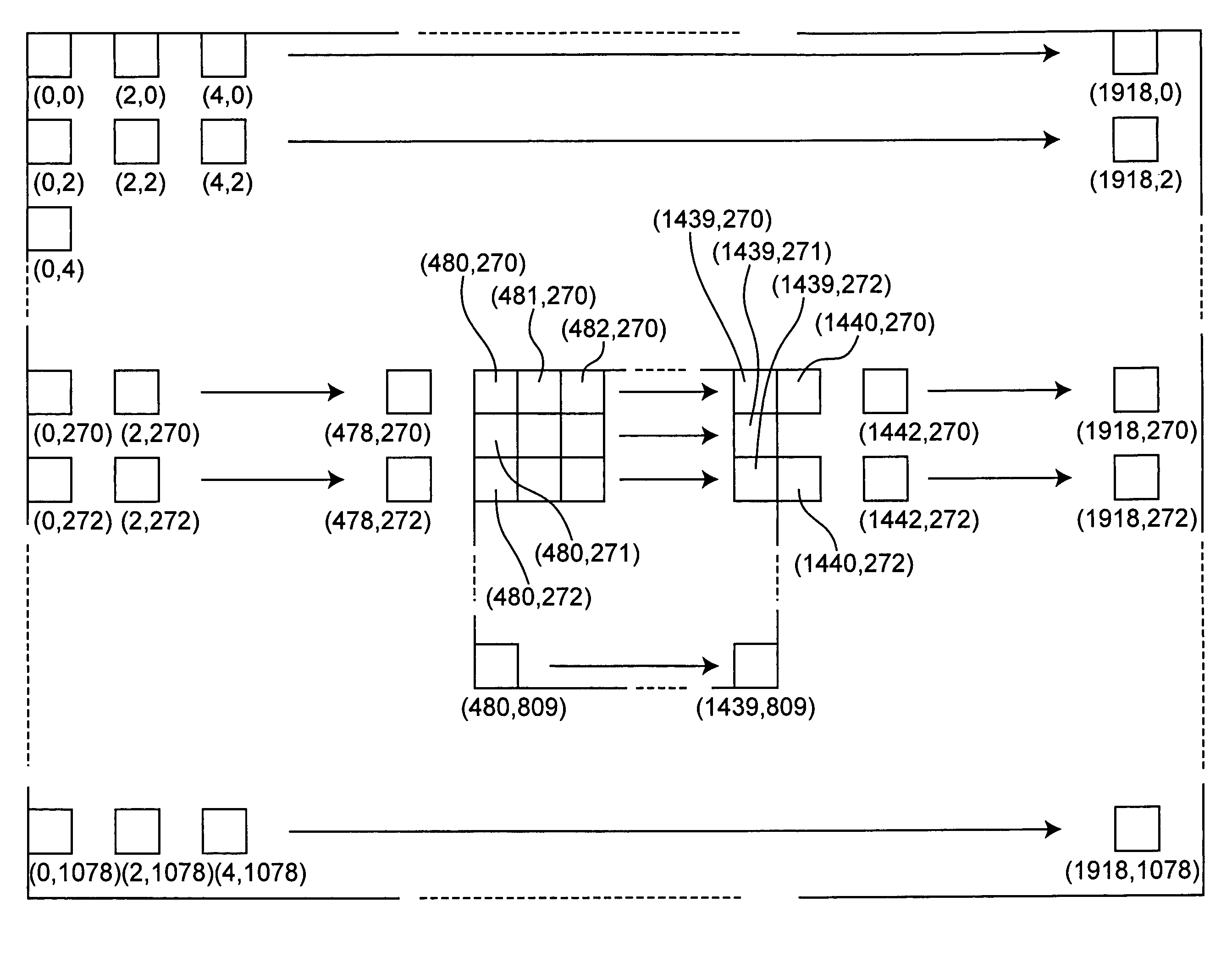
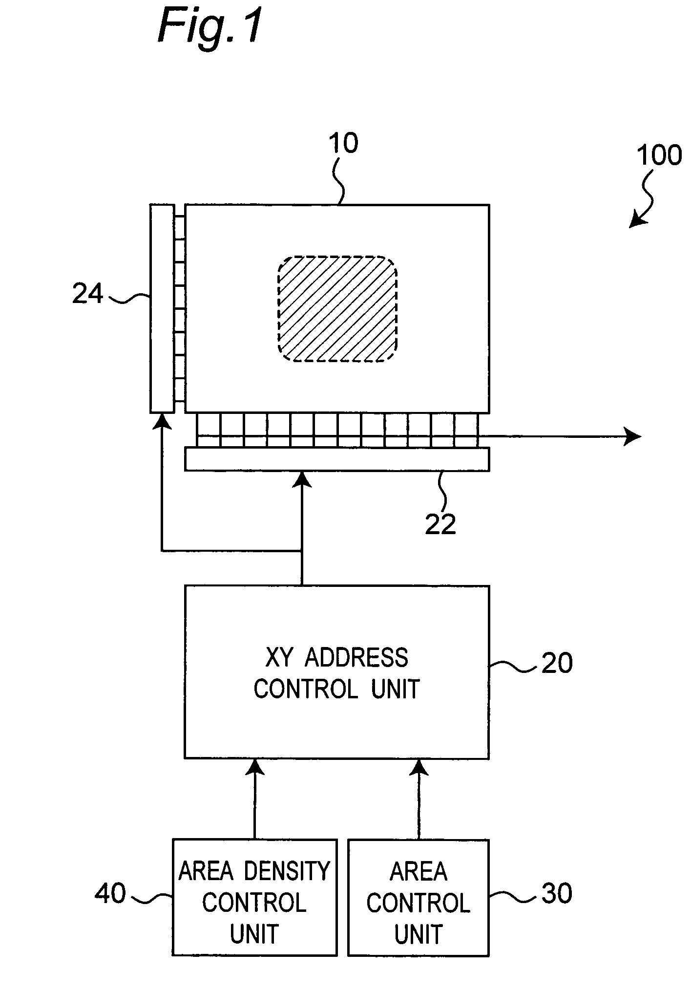
[0051]An imaging apparatus 100 according to a first embodiment of the present invention is described below with reference to FIG. 1 to FIG. 7. FIG. 1 is a block diagram of an imaging apparatus 100 according to this first embodiment of the invention.
[0052]As shown in FIG. 1, this imaging apparatus 100 has an image sensor 10, XY address control unit 20, horizontal selection circuit 22, vertical selection circuit 24, area control unit 30, and area density control unit 40.
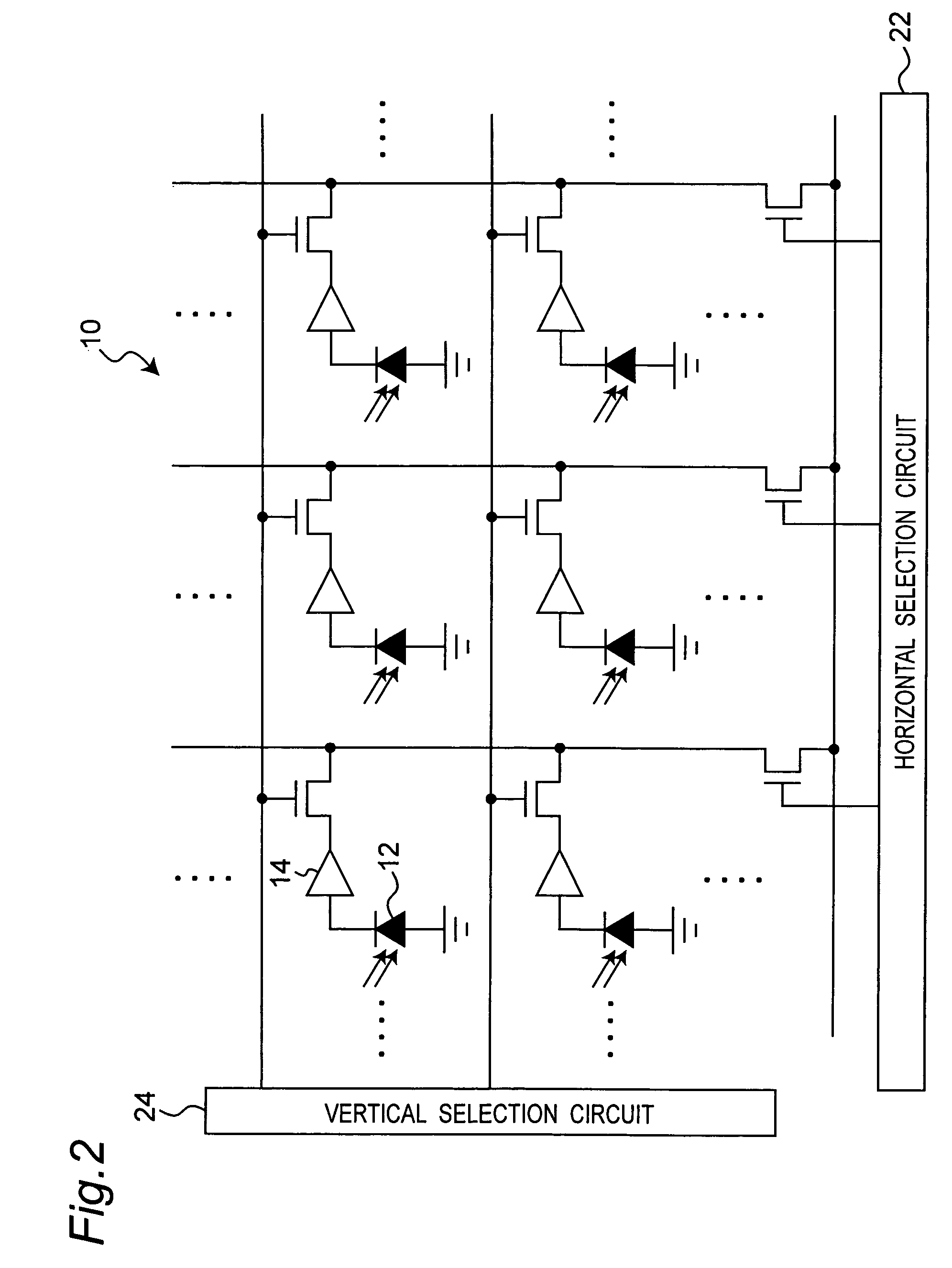
[0053]FIG. 2 is a schematic circuit diagram of the image sensor 10. This image sensor 10 is a CMOS image sensor. This CMOS sensor 10 is a two-dimensional array of pixels, each pixel having an element 12 operable to produce an electric charge by photoelectrically converting light from an imaged subject, and a part 14 operable to accumulate the produced charge and output a signal representing the accumulated charge. The elements 12 that photoelectrically convert light to produce a charge are called photodiodes. Each pixe...
embodiment 2
[0151]An imaging apparatus according to a second embodiment of the present invention is described next with reference to FIG. 20 to FIG. 23. This imaging apparatus 200 differs from the imaging apparatus of the first embodiment in pre-segmenting the total area of the image sensor 10a into a plurality of areas (area 0 to area 11 in this example), and the area density control unit 40 setting the density of pixels read from each area. The imaging apparatus 200 of this embodiment thus differs from the first imaging apparatus 100 described above in not having an area control unit because the total image area is already segmented into a plurality of areas.
[0152]FIG. 20 is a block diagram of this imaging apparatus 200. As shown in FIG. 21, the image sensor 10a is segmented into a 4×3 matrix of twelve areas, area 0 to area 11. Proceeding left to right, top to bottom from the top left area, these areas are identified sequentially from area 0, area 1, area 2 to area 11. Each area contains 172,...
PUM
 Abstract
Description
Claims
Application Information
 - R&D
- Intellectual Property
- Life Sciences
- Materials
- Tech Scout
- Unparalleled Data Quality
- Higher Quality Content
- 60% Fewer Hallucinations
Browse by: Latest US Patents, China's latest patents, Technical Efficacy Thesaurus, Application Domain, Technology Topic, Popular Technical Reports.
© 2025 PatSnap. All rights reserved.Legal|Privacy policy|Modern Slavery Act Transparency Statement|Sitemap|About US| Contact US: help@patsnap.com


