
Optical fiber

a technology of optical fiber and fiber, applied in the field of optical fiber, can solve the problems of increasing transmission loss and increasing transmission loss of optical fiber, and achieve the effect of reducing optical fiber transmission loss increase and increasing transmission loss

Inactive Publication Date: 2011-01-25
FURUKAWA ELECTRIC CO LTD
View PDF6 Cites 3 Cited by
  • Summary
  • Abstract
  • Description
  • Claims
  • Application Information

AI Technical Summary

Benefits of technology

[0011]The purpose of the present invention is, for example, to provide an optical fiber to be placed within an optical fiber cable, and more particularly to an optical fiber that reduces optical fiber transmission loss increase due to surrounding environment and / or aging. Especially, the present invention relates to a water-resistant optical fiber, which does not increase transmission loss for a long period of time even the optical fiber is placed in a high humidity environment or under water.Means for Solving Problem

Problems solved by technology

An optical fiber increases its transmission loss due to various stresses and / or micro-bends caused by those stresses.
When such optical fiber is placed under water, sometimes transmission loss increases.

Method used


Image

  • Optical fiber
  • Optical fiber
  • Optical fiber

Examples


Embodiment Construction

[0029]In the following, detailed description of the present invention is explained.

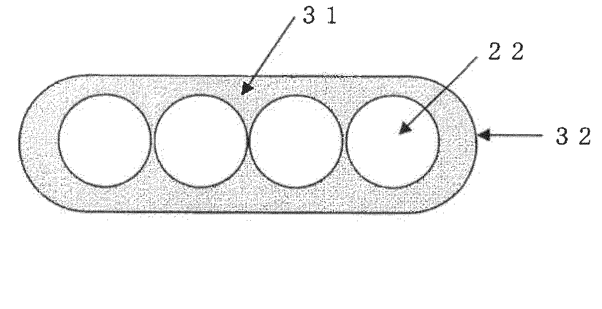
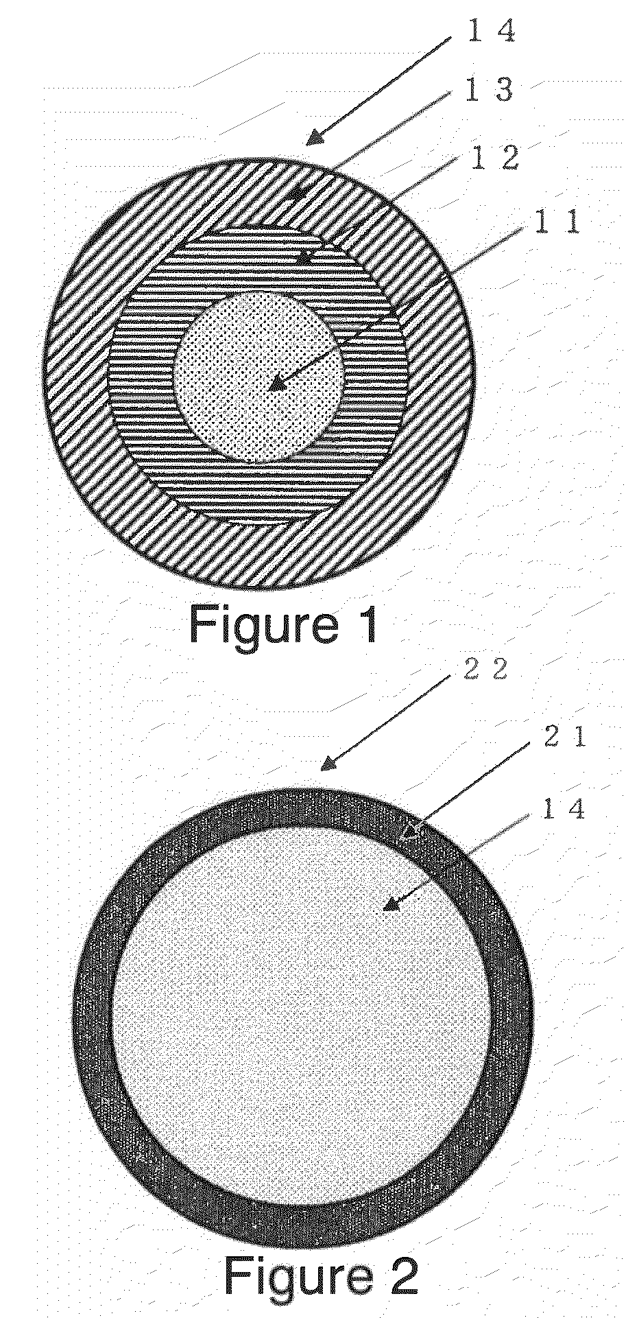
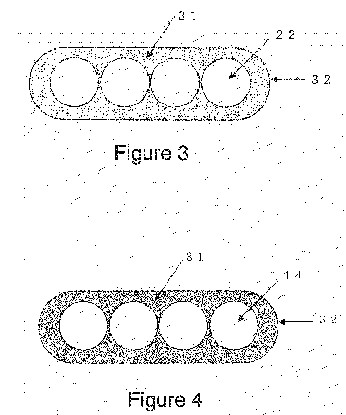
[0030]In this application, an optical fiber is defined as a glass optical fiber coated with primary and secondary layers as shown in FIG. 1. A colored optical fiber is defined as the optical fiber having a secondary layer that includes a coloring agent, or the optical fiber is further coated with an additional coating layer such as a colored resin. An optical fiber ribbon is defined as multiple colored optical fibers which are laid in parallel to one another in a linear array and held together by a ribbon resin.

[0031]Inventors for the present invention observed that an optical fiber with transmission loss increase has delaminations between a glass optical fiber and a primary layer as a result of keen examinations to find a cause of the transmission loss increase in an optical fiber under water or in a high humidity environment.

[0032]Delaminations between the glass optical fiber and the primary layer o...


PUM


Abstract

An optical fiber which reduces transmission loss increase even in a high humidity environment or under water is provided. To solve the above issue, an optical fiber according to the present invention comprises a glass optical fiber coated with at least two coating layers, soft and hard layers. The optical fiber is further coated by a colored resin to make a colored optical fiber. The hard layer and the color layer of the colored optical fiber have a free volume radius of at least 0.290 nm according to positron annihilation lifetime spectroscopy.

Description

CROSS-REFERENCES TO RELATED APPLICATIONS[0001]This application is a continuation application of International Application No. PCT / JP2008 / 054150, filed on Mar. 7, 2008, the entire contents of which are incorporated by reference herein.[0002]This application also claims the benefit of priority from Japanese Patent Application No. 2007-058833 filed Mar. 8, 2007, the entire contents of which is incorporated herein by reference.TECHNICAL FIELD[0003]The present invention relates to an optical fiber to be placed within an optical fiber cable, and more particularly to an optical fiber having reduced transmission loss increase due to surrounding environment and / or aging. In particular, the present invention relates to a water-resistant optical fiber that does not increase transmission loss for a long period of time even when the optical fiber is placed in a high humidity environment or under water.BACKGROUND OF THE INVENTION[0004]When an optical fiber is drawn from silica glass in an optical...

Claims


Application Information

Patent Timeline
Patent Type & Authority Patents(United States)
IPC IPC(8): G02B6/02
CPCG02B6/02395G02B6/4482G02B6/4403
Inventor NAKAJIMA, YASUOMOCHIZUKI, KOUJITANAKA, HIROKI
Owner FURUKAWA ELECTRIC CO LTD
Learn More