Virtual local area network pruning protocol

Active Publication Date: 2011-01-25
CISCO TECH INC
View PDF28 Cites 48 Cited by
  • Summary
  • Abstract
  • Description
  • Claims
  • Application Information

AI Technical Summary

Benefits of technology

[0020]Briefly, the present invention relates to a system and method for distributing virtual local area network (VLAN) membership information across a bridged network. In the illustrative embodiment, VLAN pruning logic is included at each port of one or more intermediate network devices, such as bridges, disposed in the bridged network. The VLAN pruning logic is configured to generate and broadcast control messages that contain VLAN membership information solely for the respective bridge, i.e., bridge-local VLAN membership information. Each VLAN pruning logic also maintains a list of VLAN designations associated with its respective port based on the receipt of control messages from other bridges in the bridged network. Also disposed at each bridge is one or more forwarding engines for determining the port(s) from which messages received at the bridge are to be transmitted, and a spanning tree protocol entity for defining one or more loop-free topologies within the network. The spanning tree protocol entities of the bridges elect a root bridge and transition the bridge's ports among a plurality of spanning tree port states, including a blocking state and a forwarding state. The VLAN pruning logic also up-dates the list of VLANs associated with the port in response to receiving a VLAN-tagged frame, provided that the corresponding port is in the forwarding state for the frame's VLAN. Notably, the VLAN pruning logic prevents the forwarding engine from transmitting a network message that is associated with a given VLAN from the respective port, unless the VLAN pruning logic has associated the given VLAN with the port, even if the port is in a forwarding state for the given VLAN.
[0021]The control messages preferably include a trigger flag, and bridges generate and transmit one or more control messages of their own in response to receiving a control message whose trigger flag is asserted. To initiate the transmission of control messages by all bridges in the network, the root bridge periodically, e.g., every TRIGGER_TIME, issues one or more control messages with the trigger flag asserted. Preferably, each bridge waits a different period of time (not exceeding a JITTER value) before responding with its own control message. Both the root bridge and non-root bridges also issue one or more contr

Problems solved by technology

Finally, the prior art methods introduce significant delay in converging to an overall result.
That is, when a new VLAN is needed at a particular bridge, there is considerable delay bef

Method used


Image

  • Virtual local area network pruning protocol
  • Virtual local area network pruning protocol
  • Virtual local area network pruning protocol

Examples


Embodiment Construction

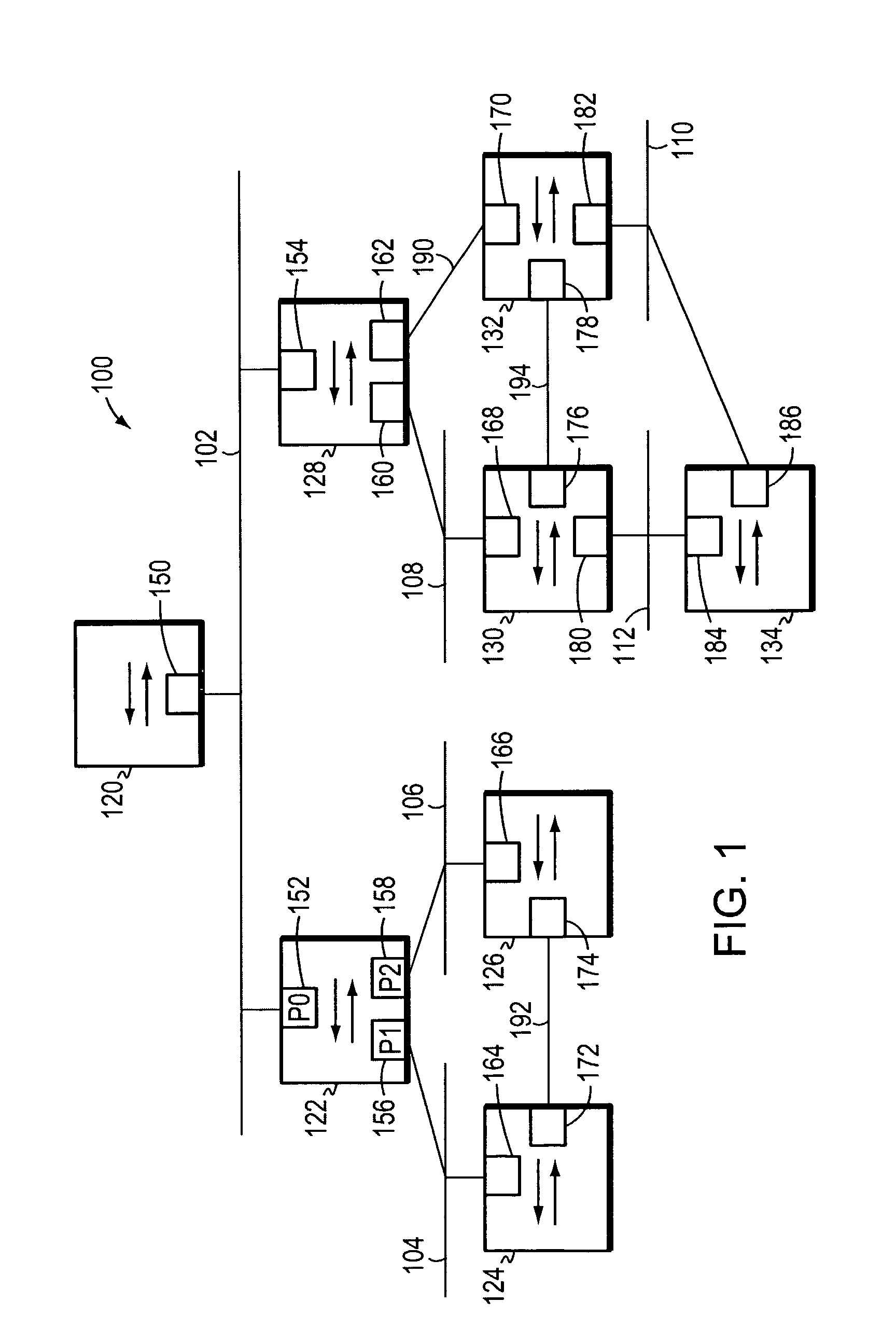
[0030]FIG. 1 is a highly schematic block diagram of a computer network 100 comprising a plurality of local area networks (LANs) 102-112 that are interconnected by a plurality of intermediate devices, such as bridges or switches 120-134. More specifically, each switch 120-134 has a plurality of ports, such as ports 150-186, and each LAN 102-112 is preferably coupled to at least one switch port 150-186. Coupled to each LAN 102-112 may be one or more end stations (not shown), such as personal computers, workstations, servers, etc. The switches 120-134 may alternatively or additionally be interconnected by one or more point-to-point links, such as point-to-point links 190-194.

[0031]It should be understood that the network 100 of FIG. 1 is meant for illustrative purposes only and that the present invention will operate with other networks having possibly far more complex topologies. For example, among other changes, one or more end stations may be directly coupled to the intermediate dev...


PUM


Abstract

In one embodiment, an intermediate network device has a plurality of ports, and at least some of the ports are associated with Virtual Local Area Network (VLAN) designations. A spanning tree entity executes a spanning tree protocol to transition the ports among a plurality of spanning tree states. A VLAN port logic circuit is disposed at one or more of the ports and processes control packets advertising VLAN memberships. The VLAN port logic circuit, in response to receiving a control packet broadcast by another intermediate network device, asserts bits in a VLAN wanted vector for which the spanning tree state of the selected port is in the forwarding state, signifying that network messages associated with such VLAN designations are to be forwarded from the respective port. The VLAN wanted vectors may later be transmitted in control messages from the intermediate network device.

Description

BACKGROUND OF THE INVENTION[0001]1. Field of the Invention[0002]The present invention relates to computer networks and, more specifically, to computer networks configured to virtually associate different network segments.[0003]2. Background Information[0004]A computer network typically comprises a plurality of interconnected entities. An entity may consist of any network device, such as a server or end station, that “sources” (i.e., transmits) or “sinks” (i.e., receives) data frames. A common type of computer network is a local area network (“LAN”) which typically refers to a privately owned network within a single building or campus. LANs typically employ a data communication protocol (LAN standard), such as Ethernet, FDDI or token ring, that defines the functions performed by the data link and physical layers of a communications architecture (i.e., a protocol stack). In many instances, several LANs are interconnected by point-to-point links, microwave transceivers, satellite hook-...

Claims


Application Information

Patent Timeline
IPC IPC(8): G06F15/16H04L12/28
CPCH04L12/4641
Inventor FINN, NORMAN W.
Owner CISCO TECH INC
Why Eureka
Try Eureka