Plastic utility shed roof system

a technology of utility sheds and roofs, applied in building roofs, walls, agricultural buildings, etc., can solve the problems of large weight, requirement of inner and outer walls, and inability to form intricate shapes and/or extrusions of plastic components, etc., and achieve the effect of convenient integral form connectors

Active Publication Date: 2011-02-01
SUNCAST
View PDF31 Cites 20 Cited by
  • Summary
  • Abstract
  • Description
  • Claims
  • Application Information

AI Technical Summary

Benefits of technology

[0014]The present invention provides a system including injection molded roof panels, headers, and ridge caps having integrated connectors which combine to form a family of variously sized roofs for utility enclosures. The roof panels, headers, and ridge caps are formed of injection molded plastic to create light-weight components having integrally formed ribs and gussets for strength and integrity. The injection molding also facilitates integrally formed connectors so that the panels, headers and ridge caps interlock with one another without the need for separate connectors. In addition, the ridge caps and / or roof panels may be formed of translucent plastic for natural lighting.
[0016]It is a further objective of the instant invention to provide a plastic roof assembly which utilizes roof panels and ridge caps having single wall construction with integrally formed ribs and gussets for a lightweight yet robust roof assembly.
[0017]It is yet another objective of the instant invention to provide a plastic roof assembly which accommodates injection molding plastic formation of the components for increased structural integrity.
[0018]It is a still further objective of the invention to provide a modular header system which allows standard components to be utilized for different width roofs.
[0021]Still yet another objective of the instant invention is to provide a roof assembly which reduces the number of components required to assemble a roof and simplifies construction.

Problems solved by technology

Unfortunately, blow molding and / or extrusion of panels for utility sheds has resulted in shortcomings within the state of the art products.
For example, due to the nature of the manufacturing process, blow molded and / or extruded plastic components cannot be formed with the intricate shapes and / or sharp corners required for integrated connectors.
Another drawback associated with blow molded panels is the requirement of an inner and an outer wall.
While the inner wall may add some rigidity to the panels, it also adds a significant amount of weight and dramatically increases the volume of plastic necessary to form a panel of a given size when compared to other methods of manufacturing, such as injection molding.
A further drawback associated with blow molded panels relates to accurate control of wall thickness throughout the panels.
The blow molding process does not allow the wall thickness of the panels to be accurately controlled.
Also, the blow molding process does not allow the intentional formation of thick and thin sections within a single panel for engineered rigidity at the points of high stress or high load concentration.
Due to the nature of the manufacturing process, the conduits are difficult to extrude in long sections for structural panels.
Wall panels utilizing these connectors are vulnerable to buckling under loads and may have an aesthetically unpleasing appearance.
Moreover, roof loads from snow and the like may cause such walls to bow outwardly due to the clearances required between the connectors and the internal bores of the conduits.
Such prior art systems, while working well, have not met all of the needs of consumers to provide the structural integrity required to construct larger sized structures.
A further problem is that the wall formed by the panels must tie into the roof and floor in such a way as to unify the entire enclosure.
There are also commercial considerations that must be satisfied by any viable utility shed enclosure system or kit; considerations which are not entirely satisfied by state of the art products.

Method used


Image

  • Plastic utility shed roof system
  • Plastic utility shed roof system
  • Plastic utility shed roof system

Examples


Embodiment Construction

[0049]While the present invention is susceptible of embodiment in various forms, there is shown in the drawings and will hereinafter be described a presently preferred embodiment with the understanding that the present disclosure is to be considered an exemplification of the invention and is not intended to limit the invention to the specific embodiments illustrated.

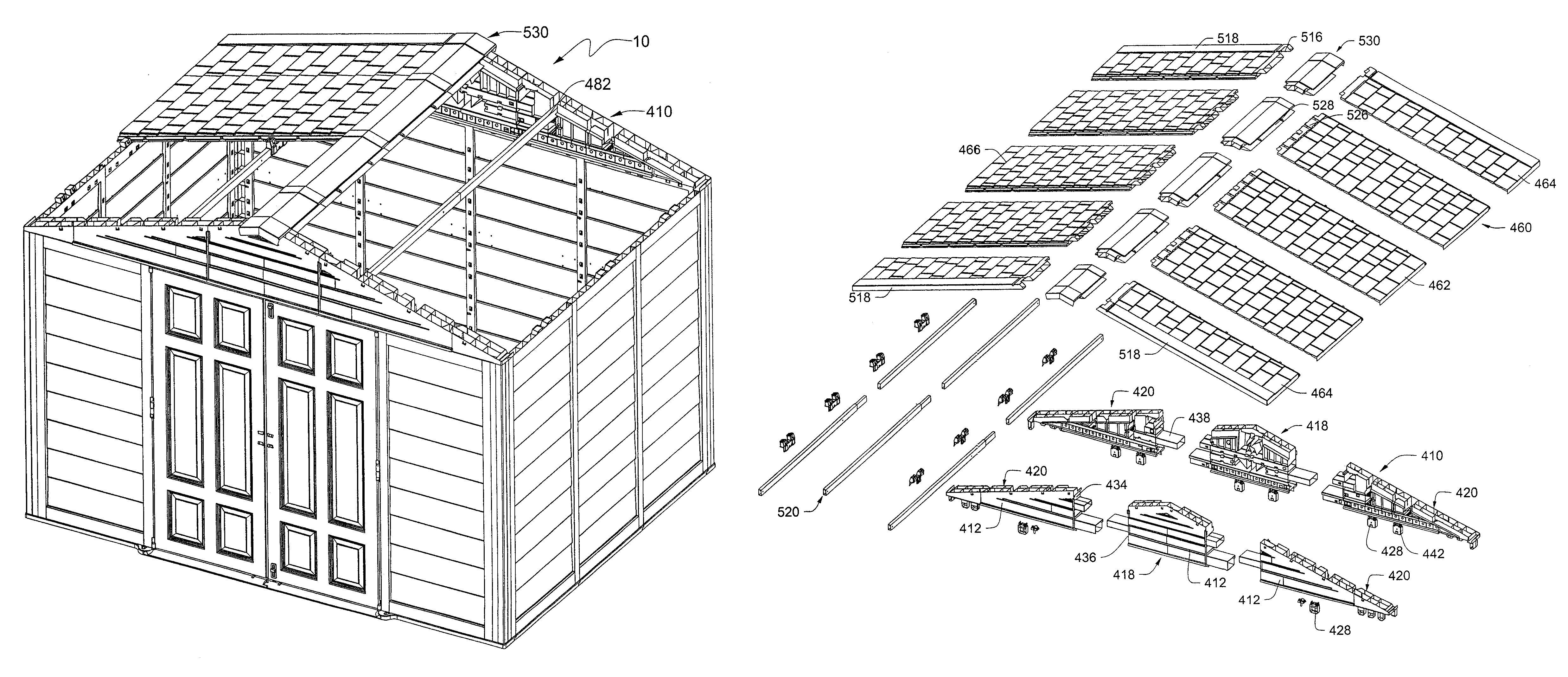
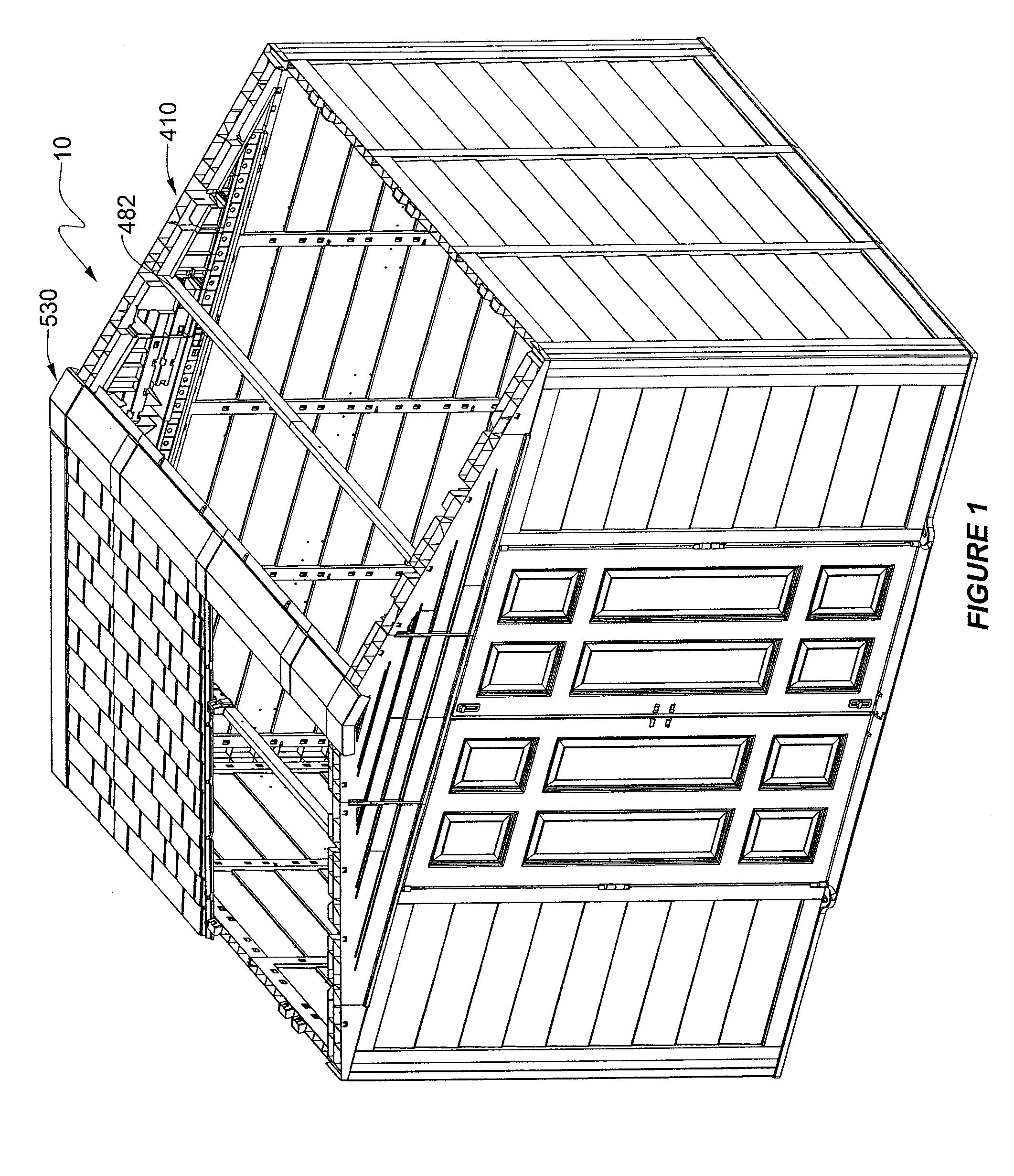
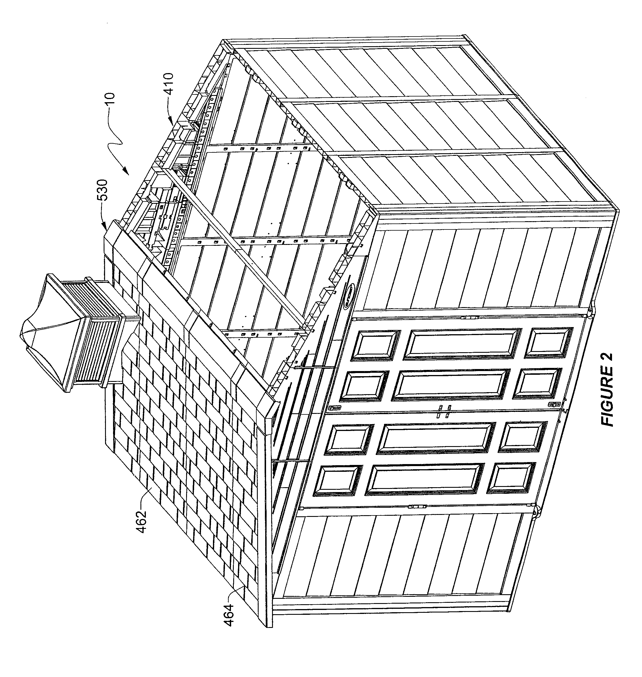
[0050]FIGS. 1-3 show perspective views of a heavy duty plastic utility enclosure, generally referenced as 10, constructed according to a preferred embodiment of the present invention. The roof assembly generally includes header assemblies 410, roof panels 460, roof supports 520, and a ridge cap assembly 530 which are shown in an exploded view in FIG. 3. The header assembly is a truss like structure molded with an aesthetically pleasing generally smooth wall 412 on its outer surface (FIGS. 3,6,7, and 9) and integrally formed box bracing 414 (FIGS. 4-9) and a plurality of pockets 416 constructed and arranged to accept roof...


PUM


Abstract

The present invention provides a system which includes injection molded roof panels, header assemblies and ridge caps having integrated connectors which combine to form a family of variously sized roof assemblies for utility enclosures. The injection molding facilitates integrally formed connectors so that the roof panels, header assemblies and ridge caps interlock with one another without the need for separate connectors.

Description

RELATED APPLICATIONS[0001]This application is a continuation of utility patent application Ser. No. 11 / 216,929 entitled Plastic Expandable Utility Shed filed Aug. 30, 2005, now U.S. Pat. No. 7,581,357 the contents of which are herein incorporated by reference in their entirety. This application is also related to Ser. No. 29 / 230,885 filed May 27, 2008, now U.S. Design Pat. No. D529,623, and Ser. No. 29 / 230,978 filed May 27, 2005, now U.S. Design Pat. No. D525,715, the contents of which are herein incorporated by reference in their entirety.FIELD OF THE INVENTION[0002]This invention relates generally to plastic utility sheds, and more specifically to a modular roof system constructed of injection molded plastic panels for creating plastic utility shed roofs of various sizes from standardized components.BACKGROUND OF THE INVENTION[0003]Utility sheds are necessary for lawn and garden care, as well as general all-around home storage space. Typically, items such as garden tractors, snow ...

Claims


Application Information

Patent Timeline
Patent Type & Authority Patents(United States)
IPC IPC(8): E04H1/12E04H1/00E04B2/08E04H5/08
CPCE04B7/20
Inventor UFFNER, MICHAELRICHARDSON, JED
Owner SUNCAST
Why Eureka
Try Eureka