
Helical conveyor without overdrive

Active Publication Date: 2011-02-01
ASHWORTH BROS
View PDF9 Cites 3 Cited by
  • Summary
  • Abstract
  • Description
  • Claims
  • Application Information

AI Technical Summary

Benefits of technology

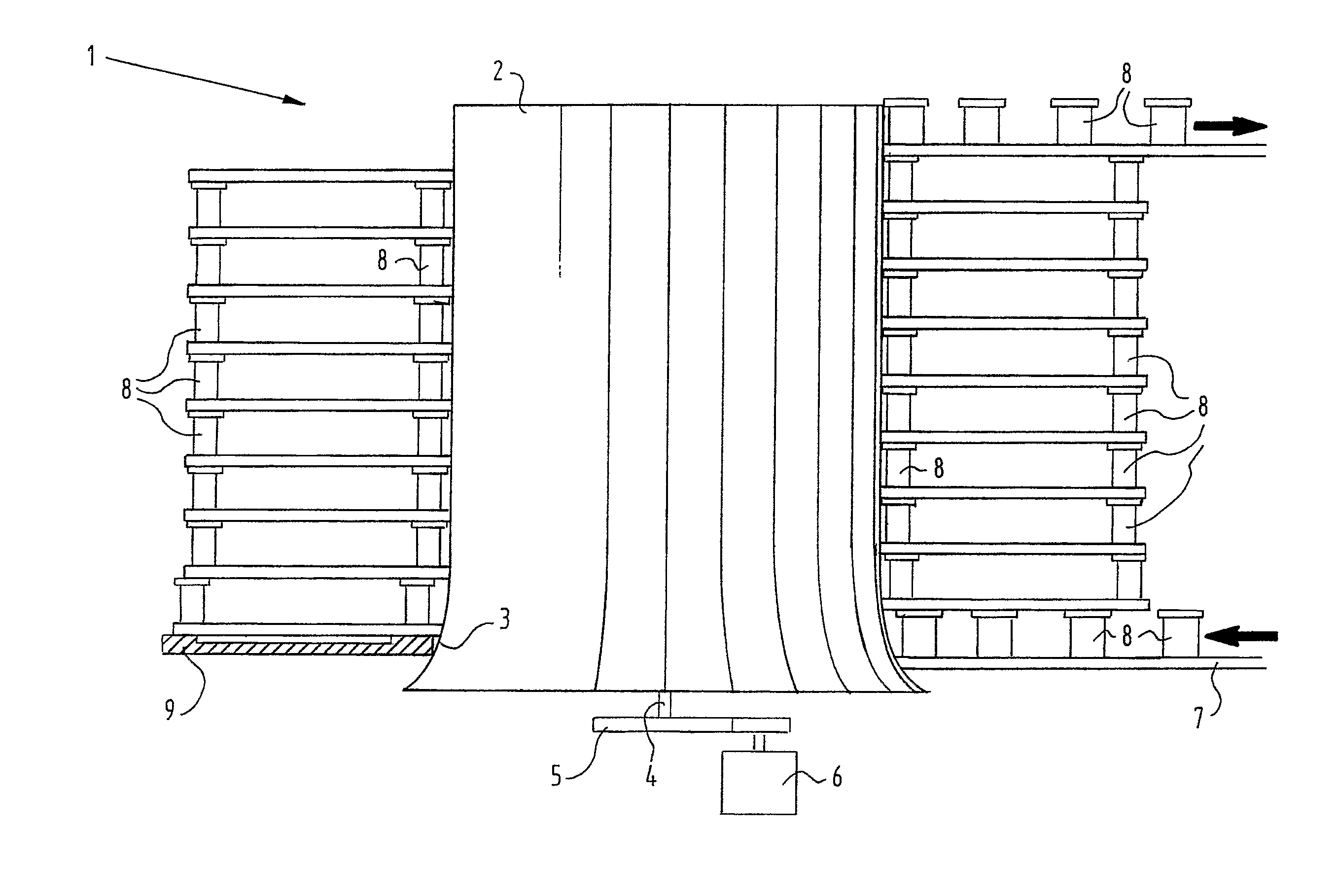
[0010]Quite unexpectedly it was shown that the tension and forces in the conveyor belt were maintained low although the conveyor belt was solely driven by the drum and no slip was available or introduced as with conveyor assemblies according to the prior art. A widened portion of the drum is provided such that the conveyor belt maintained its relative position with respect to the drum. Due to the widened portion at the bottom of the drum, the conveyor belt rests on the drum and the weight of the conveyor belt ensures that the drum is maintained at its original position. Due to the difference in diameter of the widened portion a smooth introduction of the conveyor belt into the stack of the conveyor belt is achieved. Upon introduction of the conveyor belt the peripheral velocity of the widened portion is larger than the velocity of the conveyor belt. As the conveyor belt is wound around the drum the conveyor belt is advanced upwardly to the cylindrical portion where the peripheral velocity of the cylindrical drum portion is substantially identical to the velocity of the conveyor belt. At this portion the conveyor belt will grip to the drum and the conveyor belt is driven by the drum with no significant slip.
[0014]An additional advantage of the conveyor assembly according to the invention is that no substantial black speck occurs. Black speck occurs with stackers having substantial slip between the drum and the conveyor belt. This slip provides wear of the drum resulting in substantial amounts of wear particles which will contaminate the products being conveyed. Now having eliminated substantially any slip in the conveyor assembly, no substantial wear will occur and black speck is avoided.
[0017]The conveyor assembly according to the invention can further comprise a conveyor belt having a plurality of links connected by a plurality of rods, wherein at least a number of the links comprise support elements for supporting a stacked portion of the conveyor belt. These links of the conveyor belt are preferably plastic links. Such a conveyor assembly consists out of a minimal number of parts providing a low costs conveyor assembly having a good reliability.

Problems solved by technology

Such a driving can result in very high forces in the conveyor belt resulting in early breakage of the conveyor belt.
If the forces in the conveyor belt tends to rise, the slip increases, limiting the tension and forces in the conveyor belt.
Especially when starting up such a conveyor assembly it is difficult to control the motor of the drum and the motor of the conveyor belt, such that a slip will occur and be maintained by the driving means.

Method used


Image

  • Helical conveyor without overdrive
  • Helical conveyor without overdrive

Examples


Embodiment Construction

[0019]In the drawing a conveyor assembly 1 according to the invention is shown. This conveyor assembly 1 comprises a drum 2 having a widened portion at the bottom. The cross section of this widened portion comprises a parabolic curve 3. At the shaft 4 of the drum 2 a gear wheel 5 is arranged which is driven by a motor 6. The motor 6 is considered to be a means for driving the conveyor assembly.

[0020]Rather schematic a conveyor belt 7 is shown, which is introduced at the bottom side of the drum 2 and which leaves the stack at the upper portion of the drum 2. The conveyor belt 7 comprises a number of support elements 8 which enables stacking of the conveyor belt around the drum 2. At the bottom of the stacked conveyor belt 7 a guide 9 is arranged to support the stack.

[0021]The peripheral surface of the drum 2 is smooth and the conveyor belt 7 directly abuts the smooth peripheral surface which enables a positive driving of the conveyor belt 7 without any slip on at least the cylindrica...


PUM


Abstract

The invention relates to a conveyor assembly, such as a stacker, comprising: a vertically arranged drum having a substantially smooth peripheral surface; a conveyor belt, at least one full turn wound along the peripheral surface of the drum, said belt comprising support elements to support portions of the belt on top of each other; wherein the bottom part of the drum widens outwardly and the remaining part of the drum is cylindrical.

Description

BACKGROUND OF THE INVENTION[0001]The invention relates to a conveyor assembly, commonly known as stackers. With such stackers a drum is vertically arranged and a conveyor belt is wound around the drum. The conveyor belt is driven by this drum. With a so-called full stacker the conveyor belt is stacked and supports itself. One portion of the conveyor belt supports the stacked portions on top of this supporting portion. With half stackers one side of the conveyor belt adjacent to the drum supports the stacked portions above this supporting portion and the other side of the conveyor belt is supported by a stationary guide rail.[0002]The first stacker systems used positive driving of the conveyor belt. The drum was provided with for example ribs, which engage with the sides of the conveyor belt providing a shape closed force transfer. Such a driving can result in very high forces in the conveyor belt resulting in early breakage of the conveyor belt.[0003]Another principle for driving th...

Claims


Application Information

Patent Timeline
IPC IPC(8): B65G13/02
CPCB65G21/18B65G2207/24
Inventor VAN FAASSEN, WILLEM
Owner ASHWORTH BROS
Learn More