Heart failure/hemodynamic device

a hemodynamic device and heart failure technology, applied in the field of hemodynamic assist devices, can solve the problems of large number of patients with progressive decompensated heart failure, interference with the operation of the left ventricle, and little chance of cardiac recovery

Active Publication Date: 2011-02-01
HRIDAYA
View PDF9 Cites 152 Cited by
  • Summary
  • Abstract
  • Description
  • Claims
  • Application Information

AI Technical Summary

Benefits of technology

[0009]Another embodiment of the present invention provides a method of manufacturing an implantable hemodynamic assist device that includes providing a blade member and a rotary mover. The blade member is selectively transformable between a collapsed configuration and an expanded configuration

Problems solved by technology

While recent advances in the pharmacotherapy of congestive hearts have reduced this mortality and morbidity, a large number of patients develop progressive decompensated heart failure.
During the procedure to implant a VAD, the wall of the left ventricle must be opened, resulting in an int

Method used


Image

  • Heart failure/hemodynamic device
  • Heart failure/hemodynamic device
  • Heart failure/hemodynamic device

Examples


Embodiment Construction

[0017]Referring now to the drawings, the preferred illustrative embodiments of the present invention are shown in detail. Although the drawings represent some preferred embodiments of the present invention, the drawings are not necessarily to scale and certain features may be exaggerated or partially sectioned to better illustrate and explain the present invention. Further, the embodiments set forth herein are not intended to be exhaustive or otherwise limit or restrict the invention to the precise forms and configurations shown in the drawings and disclosed in the following detailed description.

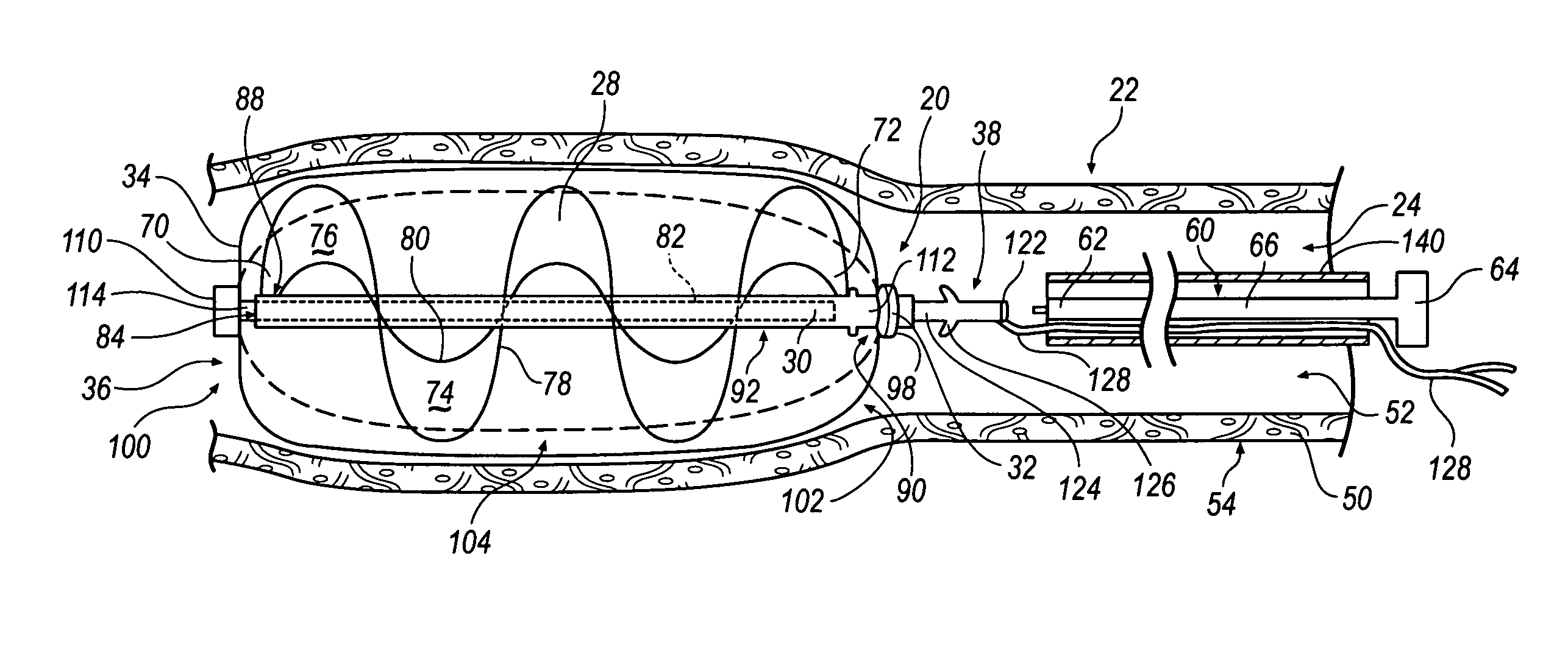
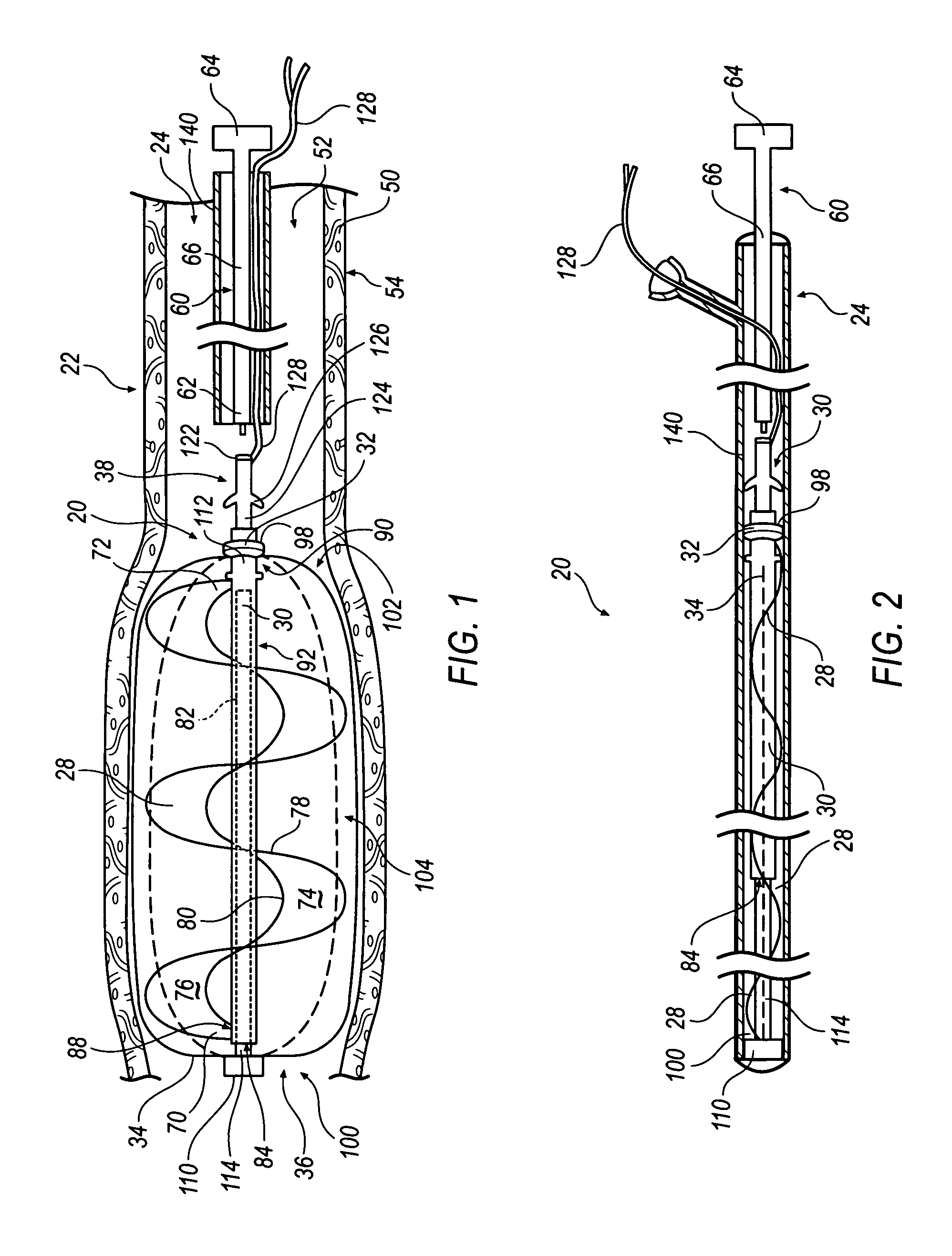
[0018]Referring to FIG. 1 a hemodynamic assist device 20 is illustrated interposed within a blood transferring conduit such as a descending aorta 22 adjacent an implantation device 24. Device 20 includes a helical blade member 28, a shaft 30, a rotary mover 32, a plurality of wires 34 forming a basket 36, and a connection end 38. Aorta 22 includes a tubular wall 50 having an inside surface 5...


PUM


Abstract

An improved hemodynamic device may be collapsed and implanted percutaneously. The device includes at least one collapsible blade member and a rotary mover for rotating the blade member to provide hemodynamic circulation. In one embodiment of the invention, the blade member rotates within a basket after implantation. The basket may be formed of shape-memory wires.

Description

TECHNICAL FIELD[0001]The present invention relates generally to hematological pumps and more specifically to a collapsible hemodynamic assist device that may be implanted and / or removed in a minimally invasive procedure.BACKGROUND[0002]Chronic heart failure (CHF) is a leading cause of mortality and morbidity in the world. The prevalence of CHF s increasing as the population ages. While recent advances in the pharmacotherapy of congestive hearts have reduced this mortality and morbidity, a large number of patients develop progressive decompensated heart failure. Typically for CHF, a pump such as a ventricular assist device (VAD) is implanted in a patient awaiting a heart transplant. The VAD is implanted as a “bridge to transplant” for those weakened hearts that are expected to become unable to pump enough blood to sustain life. A VAD is typically attached to the left ventricle and draws blood from the left ventricle and sends the blood to the aorta. During the procedure to implant a ...

Claims


Application Information

Patent Timeline
IPC IPC(8): A61M1/10F04D3/00A61M60/139A61M60/216A61M60/416A61M60/808A61M60/871
CPCA61M1/101F04D3/00F04D29/247A61M1/1024A61M1/125A61M60/148A61M60/808A61M60/139A61M60/216A61M60/416
Inventor KHANAL, SANJAYA
Owner HRIDAYA
Why Eureka
Try Eureka