Inertial separator

a separator and inner tube technology, applied in the direction of single-direction vortex, chemical/physical processes, vortex flow apparatus, etc., can solve the problems of high operating temperature, high production cost,

Active Publication Date: 2011-02-01
PALL CORP
View PDF53 Cites 32 Cited by
  • Summary
  • Abstract
  • Description
  • Claims
  • Application Information

AI Technical Summary

Problems solved by technology

However, inertial separators can be effective for undesirably short periods of time and / or expensive to produce and / or unable to withstand high operating temperatures.

Method used


Image

  • Inertial separator
  • Inertial separator
  • Inertial separator

Examples


example 1

[0080]This example demonstrates the preparation of a composition according to an embodiment of the invention.

[0081]Injection mold grade cyclic olefin copolymer (Topas® 6015S04, Topas Advanced Polymers Inc., Florence, Ky.) is mixed with powdered polyhedral oligomeric silsesquioxane (TriSilanolIsobutyl POSS®, S01450, Hybrid Plastics, Inc., Hattiesburg, Miss.), impact modifier (KRATON® G1654H SEBS polymer, Kraton Polymers U.S., LLC, Houston, Tex.), and colorant (Green Pigmented Polypropylene 0M64620047 (that includes a hindered light stabilizer and an antioxidant), Clariant, Coventry, R.I.), in a co-rotating twin screw extruder to produce pellets for use in injection molding. The percentages by weight are as follows: cyclic olefin copolymer 81%, polyhedral oligomeric silsesquioxane 3%, impact modifier 11%, and colorant 5%.

example 2

[0082]This example demonstrates that a composition according to an embodiment of the invention is suitable for producing an inertial separator.

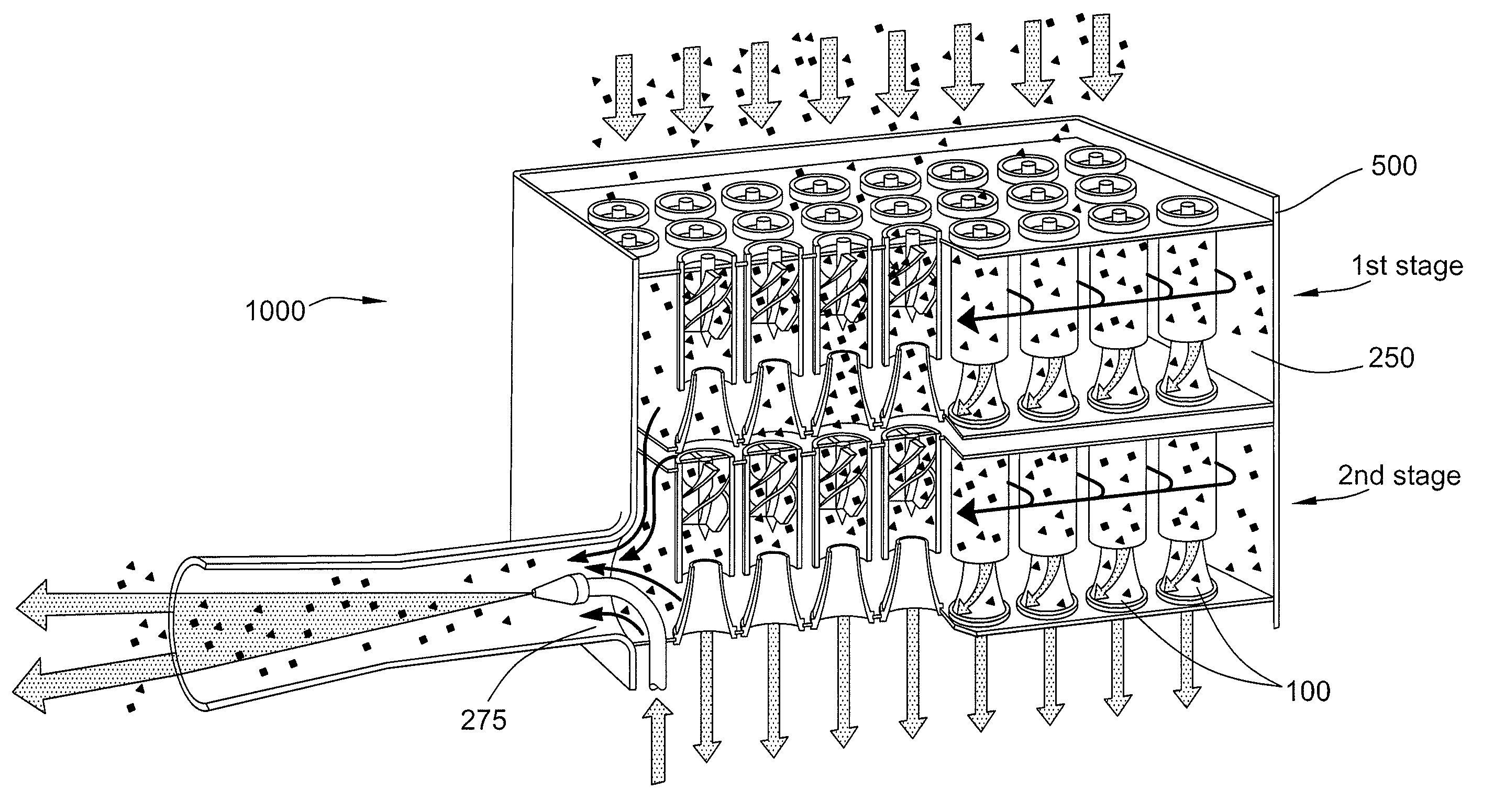
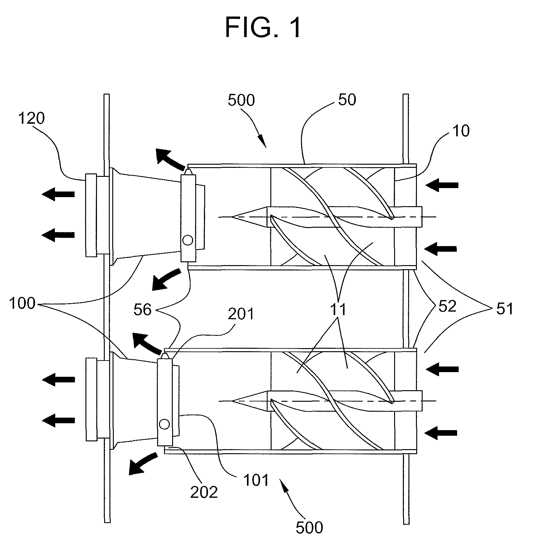
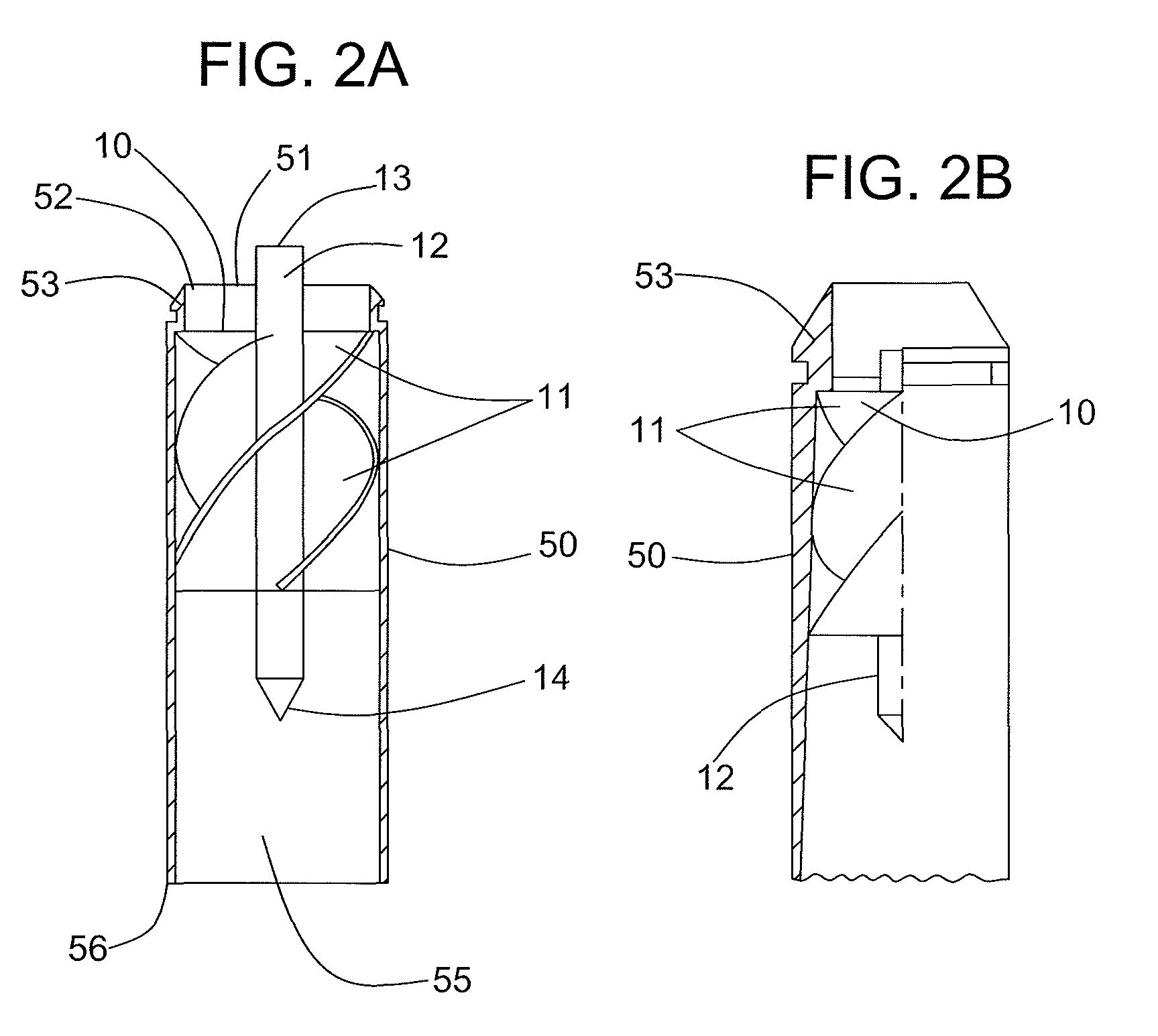
[0083]The composition according to Example 1 is injection molded to form inertial separators having the general format shown in FIGS. 1-3. The walls of the tubular housing have a thickness in the range of about 0.3 mm. The components of the separators are non-porous.

example 3

[0084]This example demonstrates the preparation of a composition according to another embodiment of the invention.

[0085]Injection mold grade cyclic olefin copolymer (Topas® 6015S04, Topas Advanced Polymers Inc., Florence, Ky.) is mixed with powdered polyhedral oligomeric silsesquioxane (TriSilanolIsobutyl POSS®, S01450, Hybrid Plastics, Inc., Hattiesburg, Miss.), impact modifier (KRATON® G1654H SEBS polymer, Kraton Polymers U.S., LLC, Houston, Tex.), flame retardant (Decabromodiphenyl Ethane Grade, Firemaster® 2100, Great Lakes Chemical Corporation, West Lafayette, Ind.), synergist (Antimony trioxide Red Star® Sb2O3, Great Lakes Chemical Corporation, West Lafayette, Ind.), mold release agent (isotactic polypropylene Hival® 2420, Ashland, Inc., Covington, Ky.), pigment (Carbon Black Vulcan 9A32, Cabot Corporation, Alpharetta, Ga.), hindered amine light stabilizer (Uvinul 5050H, BASF Corporation, Florham Park, N.J.), and antioxidant (Phenolic / Phosphite Blend Process Antioxidant, Irgan...


PUM

PropertyMeasurementUnit
angleaaaaaaaaaa
cone angleaaaaaaaaaa
lengthaaaaaaaaaa

Abstract

An inertial separator comprising a tubular body, the tubular body comprises a composition comprising a polymer selected from the group consisting of a cyclic olefin polymer and a cyclic olefin copolymer, and, a polyhedral oligomeric silsesquioxane and / or a flame retardant and / or an anti-static additive, is disclosed.

Description

CROSS-REFERENCE TO RELATED APPLICATIONS[0001]This patent application claims the benefit of U.S. Provisional Patent Application No. 60 / 975,652, filed Sep. 27, 2007, which is incorporated by reference.BACKGROUND OF THE INVENTION[0002]Engines, whether gas turbine, gasoline, diesel, or hybrid, require a flow of air into the engine during operation. Some engines, particularly in aircraft, military, or high-performance vehicles, require an extremely high flow of air into the engine. Since particulates in the air can damage the engine, inertial separators (for example, vortex air cleaners, inlet particle separators (IPS), and engine air particle separators (EAPS)) are sometimes used with engines operating under conditions where the air may contain high volumes of particulates, to remove dirt from the air entering the engines. Inertial separators are particularly useful for use with aircraft, especially turbine driven aircraft (e.g., helicopters), as when close to the ground, they stir up g...

Claims


Application Information

Patent Timeline
Patent Type & Authority Patents(United States)
IPC IPC(8): B01D45/08
CPCB01D45/12B04C3/00B04C3/06B04C5/08B04C5/103C08K5/549C08L65/00Y10T29/4973B04C2003/006Y10S55/14B01D45/16B04C3/04
Inventor LUNDQUIST, JOSEPH EDWARDTHOMAS, ALLAN
Owner PALL CORP
Why Eureka
Try Eureka