Power supply circuit, display driver, electro-optical device, and electronic instrument

a technology of power supply circuit and display driver, applied in the direction of power conversion system, dc-dc conversion, instruments, etc., can solve the problem of not being able to prevent a rush current when activating the second stag

Inactive Publication Date: 2011-02-01
SEIKO EPSON CORP
View PDF9 Cites 7 Cited by
  • Summary
  • Abstract
  • Description
  • Claims
  • Application Information

AI Technical Summary

Benefits of technology

[0011]a soft-start circuit which prevents a rush current from flowing into the flying capacitor; and
[0016]a soft-start circuit which prevents a rush current from flowing into the flying capacitor; and

Problems solved by technology

However, since a charge is not stored in the capacitor immediately before activating the charge-pump circuit, a large current (rush current) flows immediately after startup.
In this case, the technology disclosed in JP-A-2005-57860 can prevent a rush current when activating (turning ON) the first-order voltage booster circuit, but cannot prevent a rush current when activating the second-order voltage booster circuit or the like.

Method used


Image

  • Power supply circuit, display driver, electro-optical device, and electronic instrument
  • Power supply circuit, display driver, electro-optical device, and electronic instrument
  • Power supply circuit, display driver, electro-optical device, and electronic instrument

Examples


Embodiment Construction

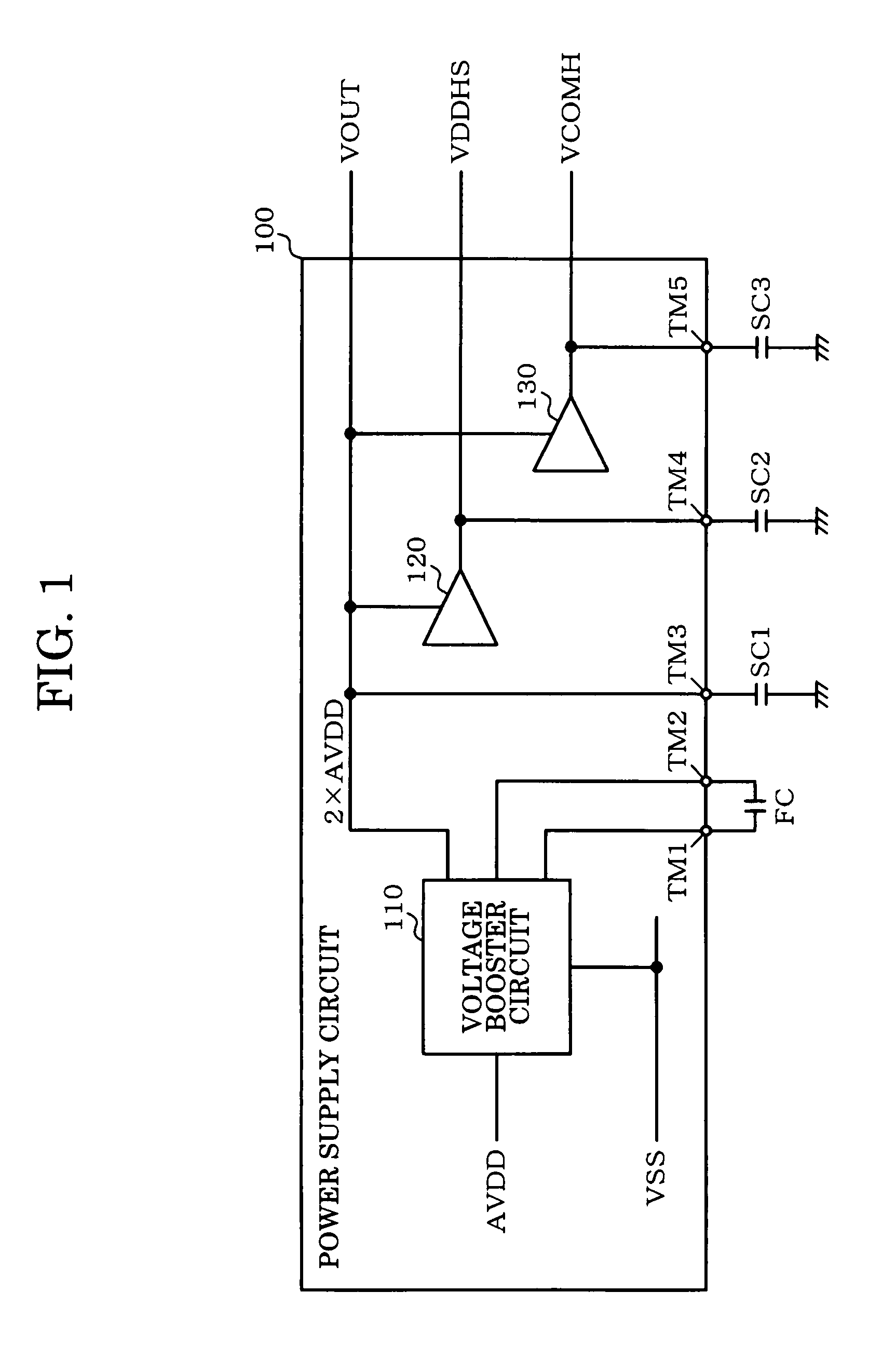
[0046]Aspects of the invention provide a power supply circuit capable of preventing a rush current even when generating power supply voltages at different timings, a display driver, an electro-optical device, and an electronic instrument.

[0047]According to one embodiment of the invention, there is provided a power supply circuit which boosts a given voltage to generate one or more power supply voltages, the power supply circuit comprising:

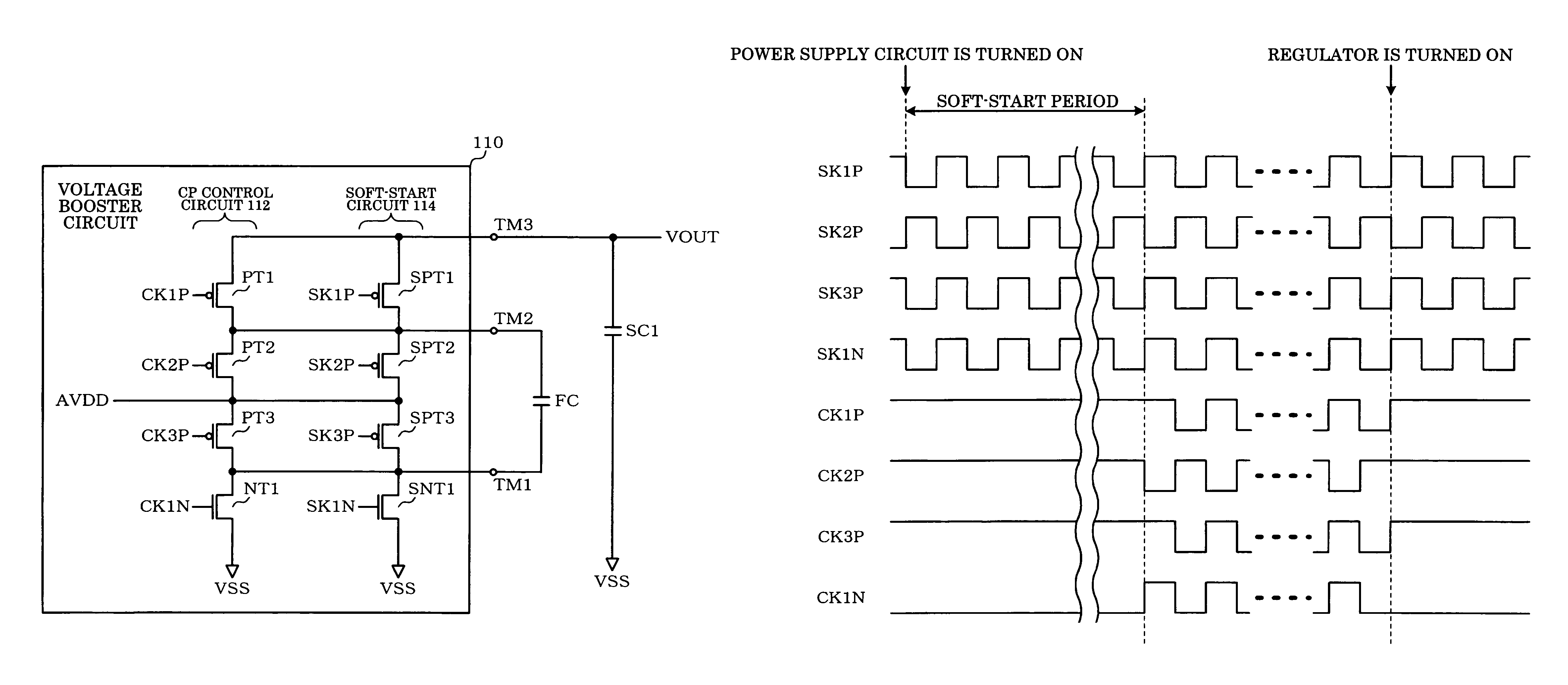
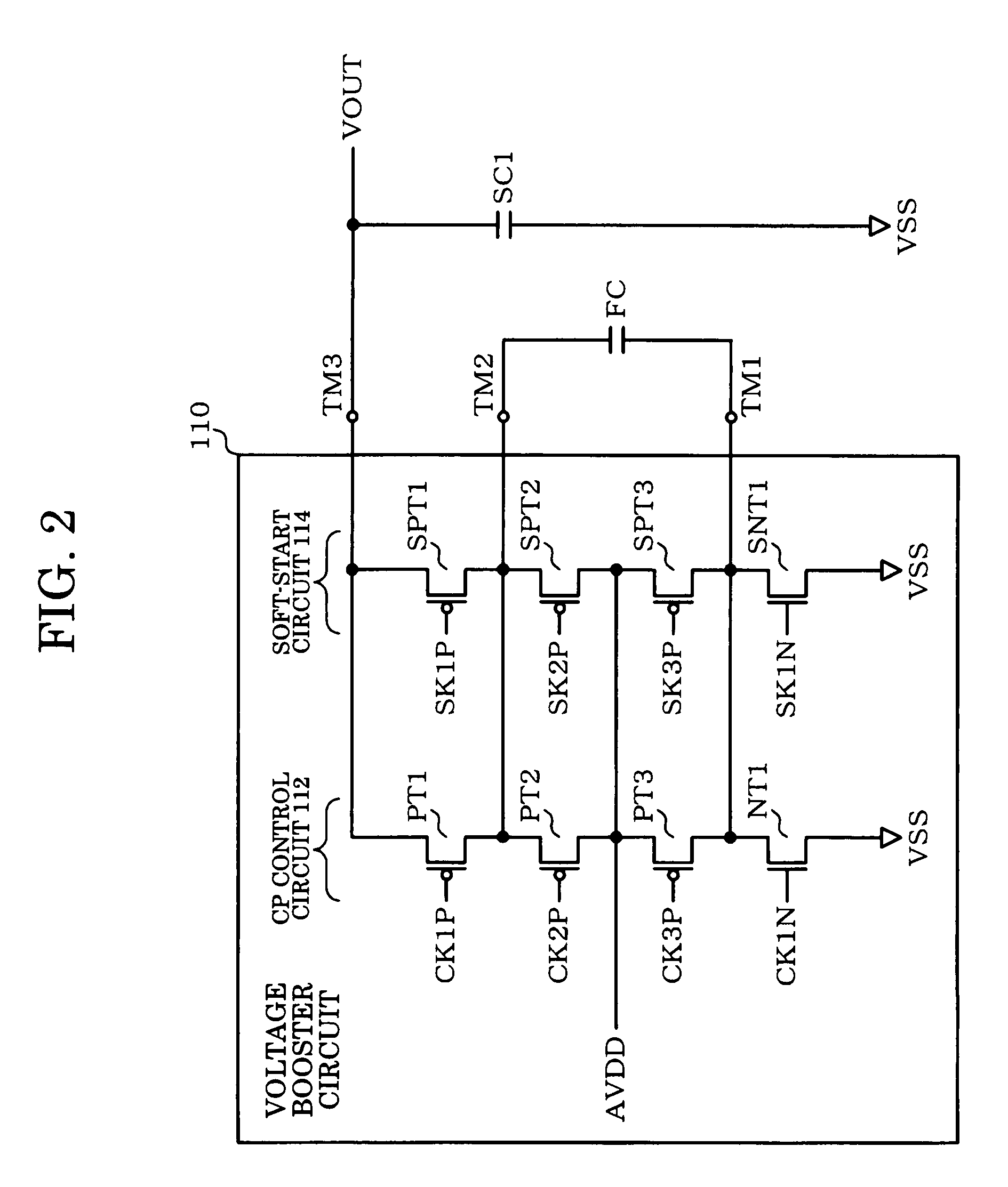
[0048]a charge-pump control circuit including switching elements for generating a boost voltage by a charge-pump operation using charge stored in a flying capacitor;

[0049]a soft-start circuit which prevents a rush current from flowing into the flying capacitor; and

[0050]a power supply generation circuit which is connected with a stabilization capacitor and generates a power supply voltage using the boost voltage as a power supply;

[0051]after the power supply generation circuit has been turned ON in a state in which the charge-pump control circuit g...


PUM

PropertyMeasurementUnit
capacitanceaaaaaaaaaa
wiring resistanceaaaaaaaaaa
voltage levelaaaaaaaaaa

Abstract

A power supply circuit which boosts a given voltage to generate one or more power supply voltages includes a charge-pump control circuit including switching elements for generating a boost voltage by a charge-pump operation using charge stored in a flying capacitor, a soft-start circuit which prevents a rush current toward the flying capacitor, and a power supply generation circuit which is connected with a stabilization capacitor and generates a power supply voltage using the boost voltage as a power supply. After the power supply generation circuit has been turned ON in a state in which the charge-pump control circuit generates the boost voltage by the charge-pump operation, the switching elements are turned OFF, and the soft-start circuit generates the boost voltage by a charge-pump operation.

Description

[0001]Japanese Patent Application No. 2006-217977 filed on Aug. 10, 2006, is hereby incorporated by reference in its entirety.BACKGROUND OF THE INVENTION[0002]The present invention relates to a power supply circuit, a display driver, an electro-optical device, and an electronic instrument.[0003]A further reduction in power consumption is demanded for portable electronic instruments. A liquid crystal device is generally used as a display device provided in such electronic instruments. A plurality of power supply voltages (e.g. high voltage and negative voltage) are required to drive the liquid crystal device. In this case, it is desirable from the viewpoint of cost that a liquid crystal driver device which drives the liquid crystal device include a power supply circuit which generates power supply voltages.[0004]Such a power supply circuit includes a voltage booster circuit. A charge-pump circuit which generates a voltage boosted by a charge-pump operation is generally employed as th...

Claims


Application Information

Patent Timeline
Patent Type & Authority Patents(United States)
IPC IPC(8): H02M3/18H02M7/00G05F1/10G02F3/02
CPCH02M3/07
Inventor ISHIYAMA, HISANOBU
Owner SEIKO EPSON CORP
Why Eureka
Try Eureka